3. Chec k and adjust all castor tire pressures to 50
psi (345 kP a).
4. Chec k c harg e and counterbalance pressures
with engine at high idle using test por ts defined
in Hy draulic Systems T est P or ts . Adjust
counterbalance setting to be 230 psi (1585 kP a)
higher than c harg e pressure reading .
5. Chec k for bent blades; refer to Chec king for a
Bent Blade procedure in Mo w er Maintenance ,
pag e 51 .
6. Cut g rass in a test area to deter mine if all
cutting units are cutting at the same height.
7. If cutting unit adjustments are still needed, find
a flat surface using a 6 foot (2 m) or long er
straight edg e .
8. T o ease measuring blade plane , raise the
height of cut to the highest position; refer to
Adjusting the Height of Cut.
9. Lo w er cutting units onto the flat surface .
R emo v e the co v ers from the top of the cutting
units .
10. Loosen the flang e n ut, securing the idler pulley ,
to release the belt tension on eac h cutting unit.
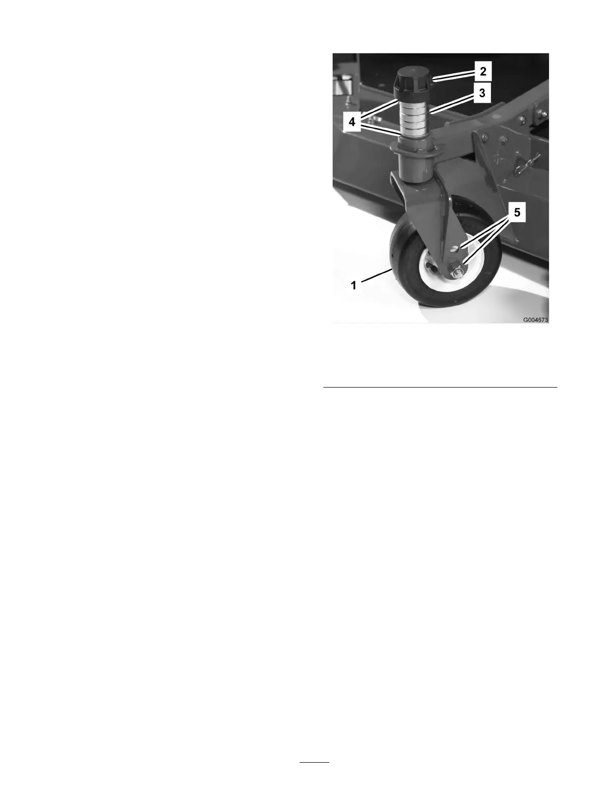
Center Cutting Unit Setup
R otate blade on eac h spindle until the ends face
forw ard and bac kw ard. Measure from the floor to
the front tip of the cutting edg e . Adjust 1/8 inc h
shims on front castor fork(s) to matc h height of cut
to decal ( Figure 26 ); refer to Adjusting the Cutting
Unit Pitc h procedure in Mo w er Maintenance ,
pag e 51 .
Figure 26
1. Castor wheel 4. Shims
2. Tensioning cap
5. Axle mounting holes
3. Spacers
W ing Cutting Unit Setup
R otate blade of eac h spindle until the ends face
forw ard and bac kw ard. Measure from the floor
to the front tip of the cutting edg e . Adjust 1/8
inc h shims on front castor ar m(s) to matc h height
of cut to decal ( Figure 27 ). F or the outside blade
spindle only , refer to Adjusting the Cutting Unit
Pitc h procedure in Mo w er Maintenance , pag e 51 .
27