Belt Maintenance
Servicing the Alternator Belt
Chec k the condition and tension of the belts
( Figure 63 ) after ev er y 100 operating hours .
1. Proper tension will allo w 3/8 inc h (10 mm)
deflection when a force of 10 lb is applied on
the belt midw a y betw een the pulleys .
2. If the deflection is not 3/8 inc h (10 mm),
loosen the alter nator mounting bolts
( Figure 63 ). Increase or decrease the alter nator
belt tension and tighten the bolts . Chec k the
deflection of the belt ag ain to ensure that the
tension is cor rect.
Figure 63
1. Alternator 2. Mounting bolt
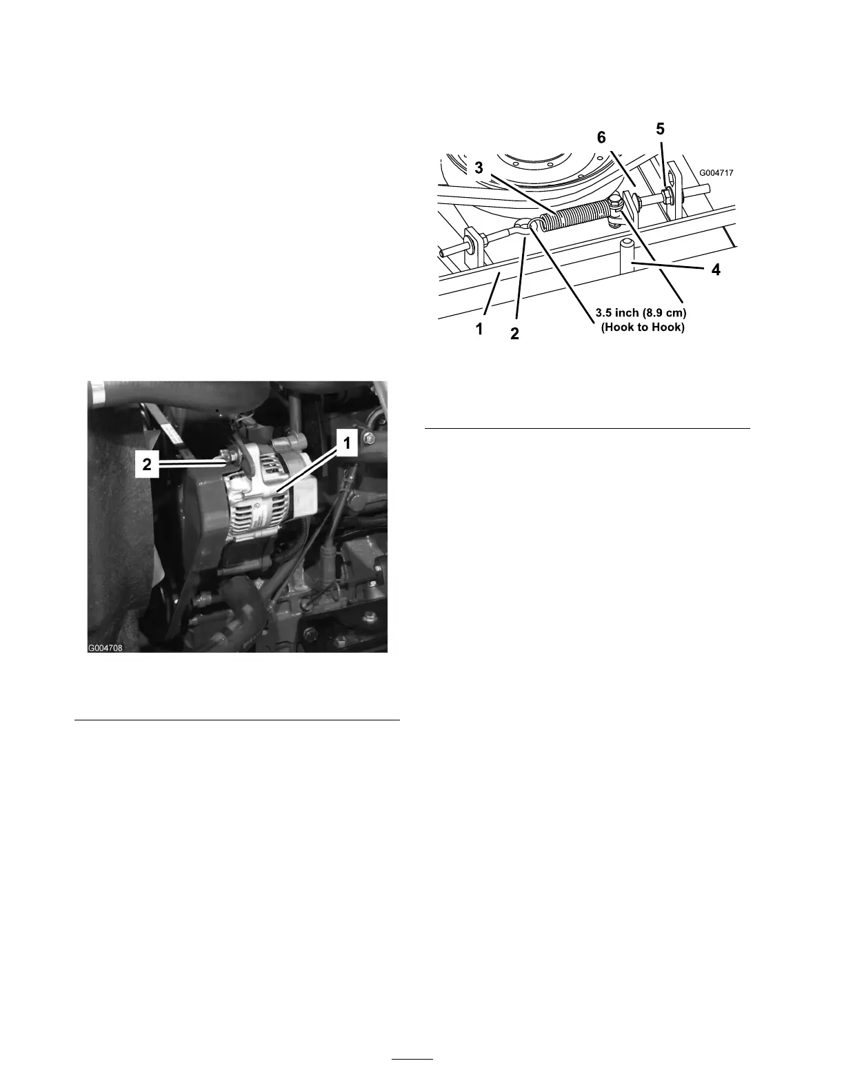
Re-tensioning the Blade
Drive Belts
Chec k the condition and tension of the cutting
unit dri v e belts initially after 8 hours of operation
and ev er y 50 operating hours thereafter .
W hen properly tensioned, the extension
spring (hook to hook) measurement should be
appro ximately 3.50 ±.25 inc h (inside). Once the
cor rect spring tension is attained, adjust the stop
bolt (car riag e bolt) until there is appro ximately
.125 +.060/-.000 inc h clearance betw een the head
of the bolt and the idler ar m ( Figure 64 ).
Note: Mak e sure the belt is positioned on the
spring side of the belt guide ( Figure 64 ).
Figure 64
1. Belt 4. Belt guide
2. Eye bolt 5. Flange nut
3. Extension spring
6. Stop bolt
Replacing the Blade Drive
Belt
T he blade dri v e belt, tensioned b y the spring
loaded idler pulley , is v er y durable . Ho w ev er , after
many hours of use , the belt will sho w signs of
w ear . Signs of a w or n belt are: squealing when
belt is rotating, blades slipping when cutting g rass ,
fra yed edg es , bur n marks and crac ks . R e place the
belt if any of these conditions are evident.
1. Lo w er the cutting unit to the shop floor .
R emo v e the belt co v ers from the top of the
cutting unit and set the co v ers aside .
2. Loosen the eye bolt allo wing the remo v al of
the extension spring ( Figure 64 ).
3. Loosen the flang e n ut securing the stop bolt
to the mounting tab . Bac k off the n ut enough
to allo w the idler ar m to pass b y the stop bolt
( Figure 64 ). Mo v e the idler pulley a w a y from
the belt to release belt tension.
Note: If the stop bolt is ev er remo v ed from
the mounting tab , mak e sure it is reinstalled
in the hole that aligns the stop bolt head with
the idler ar m.
4. R emo v e the bolts securing the h y draulic motor
to the cutting unit ( Figure 65 ). Lift the motor
off of the cutting unit and la y it on top of the
cutting unit.
46