If the blade is allo w ed to w ear , a slot
will f or m betw een the sail and flat par t
of the blade ( Figur e 93 ). Ev entuall y a
piece of the blade may br eak of f and be
thr o wn fr om under the housing , possibl y
r esulting in serious injur y to y ou or
bystander s.
• Inspect the blade periodicall y f or
w ear or dama ge.
• Nev er tr y to straighten a blade that
is bent or w eld a br ok en or crack ed
blade.
• R eplace a w or n or dama ged blade.
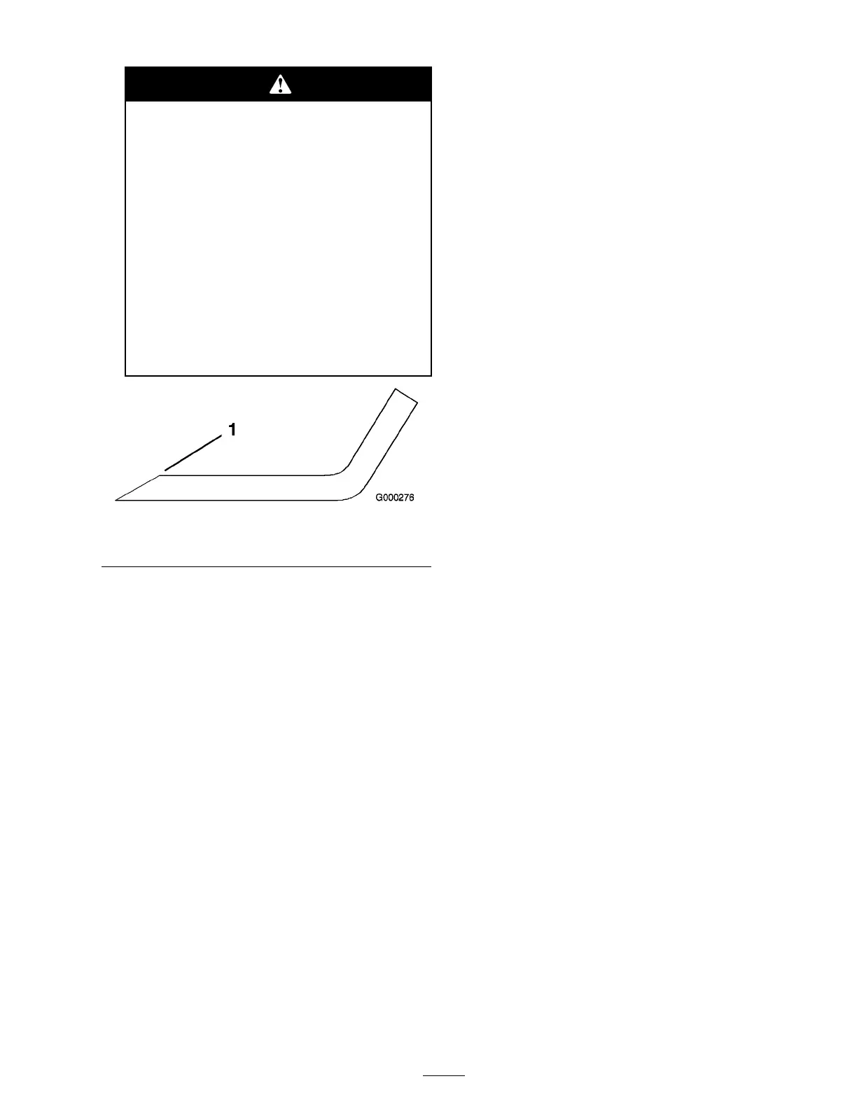
Figure 94
1. Sharpen at original angle
Note: R emo v e the blades and shar pen them
on a g rinder . After shar pening the cutting
edg es , install the blade with the anti-scalp
cup and blade bolt; refer to R emo ving and
Installing the Cutter Blade(s).
Correcting Cutting Unit
Mismatch
If there is mismatc h betw een the blades , on a
single cutting unit, the g rass will appear streak ed
when it is cut. T his problem can be cor rected b y
making sure that the blades are straight and all of
the blades are cutting on the same plane .
1. Using a 3 foot (1 meter) long car penters lev el,
find a lev el surface on the shop floor .
2. Raise the height-of-cut to the highest position;
refer to Adjusting the Height-Of-Cut.
3. Lo w er the cutting unit onto the flat surface .
R emo v e the co v ers from the top of the cutting
unit.
4. Loosen the flang e n ut securing the idler pulley
to release the belt tension.
5. R otate the blades until the ends face forw ard
and bac kw ard. Measure from the floor to the
front tip of the cutting edg e . R emember this
dimension. T hen rotate the same blade so
that the opposite end is forw ard, and measure
ag ain. T he difference betw een the dimensions
m ust not ex ceed 1/8 inc h (3 mm). If the
dimension ex ceeds 1/8 inc h (3 mm), re place
the blade because it is bent. Mak e sure to
measure all of the blades .
6. Compare the measurements of the outer blades
with the center blade . T he center blade m ust
not be more than 3/8 inc h (10 mm) lo w er
than the outer blades . If the center blade is
more than 3/8 inc h (10 mm) lo w er than the
outer blades , proceed to ste p 7 and add shims
betw een the spindle housing and the bottom
of the cutting unit.
7. R emo v e the bolts , flat w ashers , loc k w ashers ,
and n uts from the outer spindle in the area
where the shims m ust be added. T o raise or
lo w er the blade , add a shim, P ar t No . 3256-24,
betw een the spindle housing and the bottom
of the cutting unit. Contin ue to c hec k the
alignment of the blades and add shims until
the tips of the blades are within the required
dimension.
Important: Do not use mor e than
thr ee shims at an y one hole location. Use
decr easing n umber s of shims in adjacent
holes if mor e than one shim is added to
an y one hole location.
8. Adjust the idler pulley and install the belt
co v ers .
Spark Arrestor
Maintenance
Servicing the Spark Arrestor
Mufer
Ev er y 200 hours operation, clear the m uffler of
carbon buildup .
1. R emo v e the pipe plug from the clean-out por t
at the lo w er side of the m uffler .
57