6.Inspectthecasterwheelforkforwearandreplace
ifnecessary(Figure43).
7.Slidethecasterwheelforkthroughthebushingsin
themountingtube.Replacethespacer(s)ontothe
forkandsecurewiththeretainingring(Figure43).
Important:Theinsidediameterofthebushings
maycollapseslightlywheninstalled.Ifthe
casterwheelforkdoesnotslideintothenew
bushings,reambothbushingstoaninside
diameterof1.126inch(29mm).
8.Greasethettingonthecarrierframepivottubes
usingNo.2generalpurposelithiumbaseor
molybdenumbasegrease.
ServicingtheCasterWheel
andBearings
Thecasterwheelsrotateonarollerbearingsupportedby
aspannerbushing.Ifthebearingiskeptwelllubricated,
wearwillbeminimal.Failuretokeepthebearingwell
lubricatedwillcauserapidwear.Awobblycasterwheel
usuallyindicatesawornbearing.
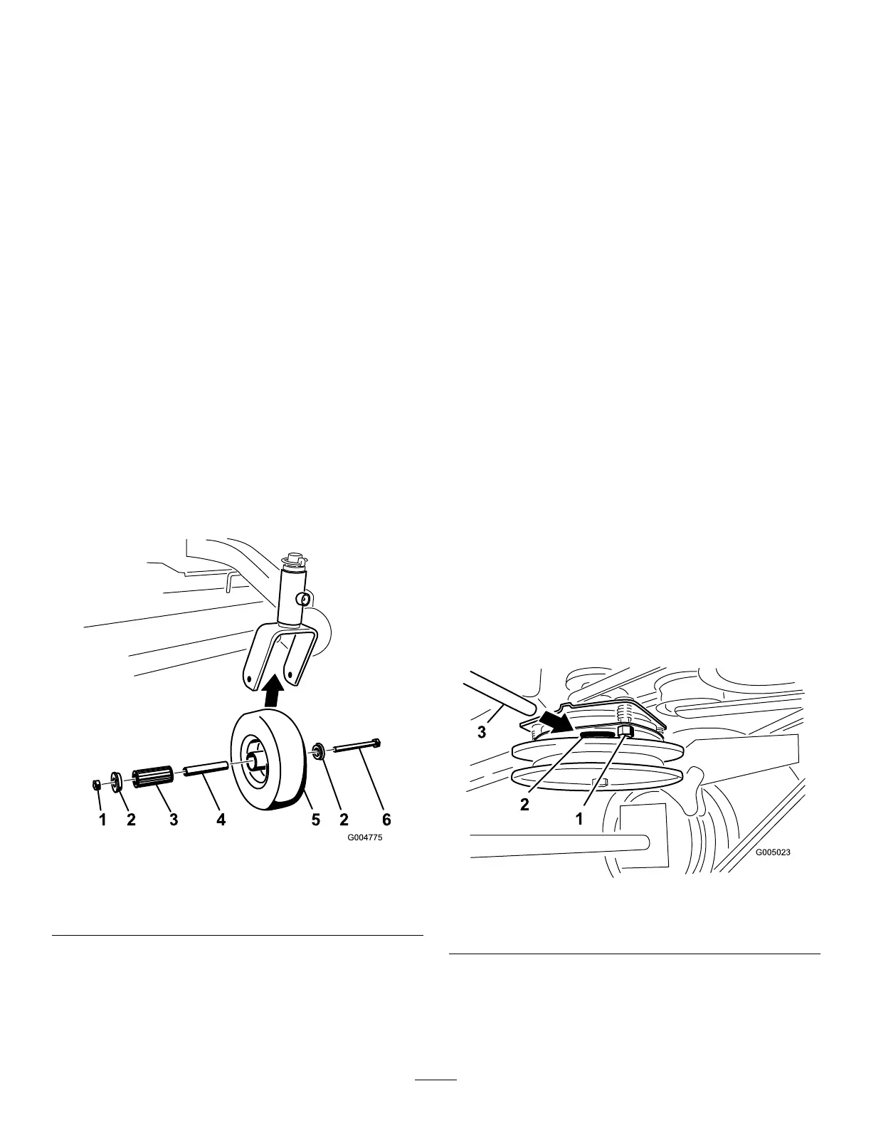
1.Removethelocknutandwheelboltholdingthe
casterwheeltothecasterfork(
Figure45).
Figure45
1.Locknut
4.SpannerBushing
2.WheelBolt5.RollerBearing
3.Bushing
2.Removeonebushing,thenpullthespannerbushing
androllerbearingoutofthewheelhub(Figure45).
3.Removetheotherbushingfromthewheelhub
andcleananygreaseanddirtfromthewheelhub
(Figure45).
4.Inspecttherollerbearing,bushings,spannerbushing
andinsideofthewheelhubforwear.Replaceany
defectiveorwornparts(
Figure45).
5.Toassemble,placeonebushingintothewheelhub.
Greasetherollerbearingandspannerbushingand
slidethemintothewheelhub.Placethesecond
bushingintothewheelhub(
Figure45).
6.Installthecasterwheelintothecasterforkand
securewiththewheelboltandlocknut.Tightenthe
locknutuntilthespannerbushingbottomsagainst
theinsideofthecasterforks(
Figure45).
7.Greasethettingonthecasterwheel.
AdjustingtheElectricClutch
ServiceInterval:Every100hours
Theclutchisadjustabletoensureproperengagement
andproperbraking.
1.Inserta0.015–0.021inch(0.381–0.533mm)feeler
gaugethroughoneinspectionslotinthesideofthe
assembly.Makesureitisbetweenthearmatureand
therotorfrictionsurfaces.
2.Tightenthelocknutsuntilthereisslightbindingon
thefeelergaugebutitcanbemovedeasilywithinthe
airgap(
Figure46).
3.Repeatthisfortheremainingslots.
4.Checkeachslotagainandmakeslightadjustments
untilthefeelergaugebetweentherotorandarmature
withveryslightcontactbetweenthem.
Figure46
1.Adjustingnut3.Feelergauge
2.Slot
35