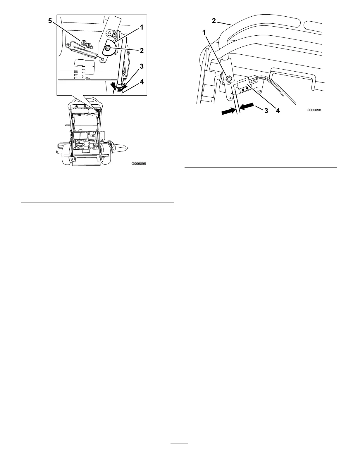
Figure55
1.Cam
4.Turnbuckle
2.Nutandbolt
5.Switchscrews
3.Wingnut
9.Afterthecamisadjusted,theleverswitchneedsto
bechecked.
10.Checkthegapbetweenthecontrolleverandswitch
asshownin
Figure56.Thegapneedstobebetween
a1/16inchto3/32inch(1.6mmto2.4mm).
11.Ifneeded,loosenthescrewsholdingtheswitchand
adjusttheswitch.
12.Tightenthescrewsandinstallthecoverunderthe
controlpanel.
Figure56
1.Rightsidemotioncontrol
leverpivotshownunder
controls
3.1/16inchto3/32inch
(1.6mmto2.4mm)gap
neededbetweenswitch
andcontrollever
2.Rightsidemotioncontrol
lever
4.Switch
AdjustingtheNeutralPostionforthe
MotionControlLevers
Important:Ensurethetrackingofthemoweris
correctafteradjustingthemotioncontrollevers.
Afteradjustingthetracking,themotioncontrol
leversmaynotaligntheexactlyfronttoback
(
Figure57).
Ifthemotioncontrolleversdonotalignfronttoback,
ortherightsidecontrolleverdoesnotmoveeasilyinto
theneutrallockposition,adjustmentisrequired.Adjust
eachleverandcontrolrodseparately.
Note:Adjustthehorizontalalignmentbeforethefront
tobackalignment.
1.Afterthehorizontalalignmentisnished,checkthe
fronttobackalignment(
Figure57).
41