Figure57
1.Leftmotioncontrollever
3.Neutrallockedposition
2.Rightmotioncontrollever4.Alignthecontrollevers
fronttobackhere
2.Loosenthewingnutsontherightcontrolrodand
rotatetheturnbuckleinorouttoensuretheright
sidecontrolleveriscenteredintheneutrallock
position.Securetheturnbuckleinpositionwiththe
wingnuts(Figure58).
3.Loosenthewingnutsontheleftcontrolrodand
rotatetheturnbuckleinorouttochangethetracking.
Securetheturnbuckleinpositionwiththewingnuts
(
Figure58).
Figure58
1.Turnbuckle
3.Topwingnut(lefthand
threaded)
2.Bottomwingnut
4.Checkforpropertracking.Adjusttheleftcontrol
rodifachangeisneeded.RefertoAdjustingthe
TrackingintheOperationSection.
HydraulicSystem
Maintenance
ServicingtheHydraulic
System
CheckingtheHydraulicFluid
ServiceInterval:Aftertherst8hours
Every25hours
Note:Therearetwowaysofcheckingthehydraulicoil.
Oneiswhentheoiliswarmandoneiswhentheoilis
cold.Thebafeinsidethetankhastwolevelsdepending
iftheoiliswarmorcold.
1.Positionmachineonalevelsurface.
2.Disengagethepowertakeoff(PTO)andshutoff
theengine.
3.Waitforallmovingpartstostopbeforeleavingthe
operatingpositionandthensettheparkingbrake.
4.Cleanareaaroundcapandllerneckofhydraulic
tank(
Figure59).
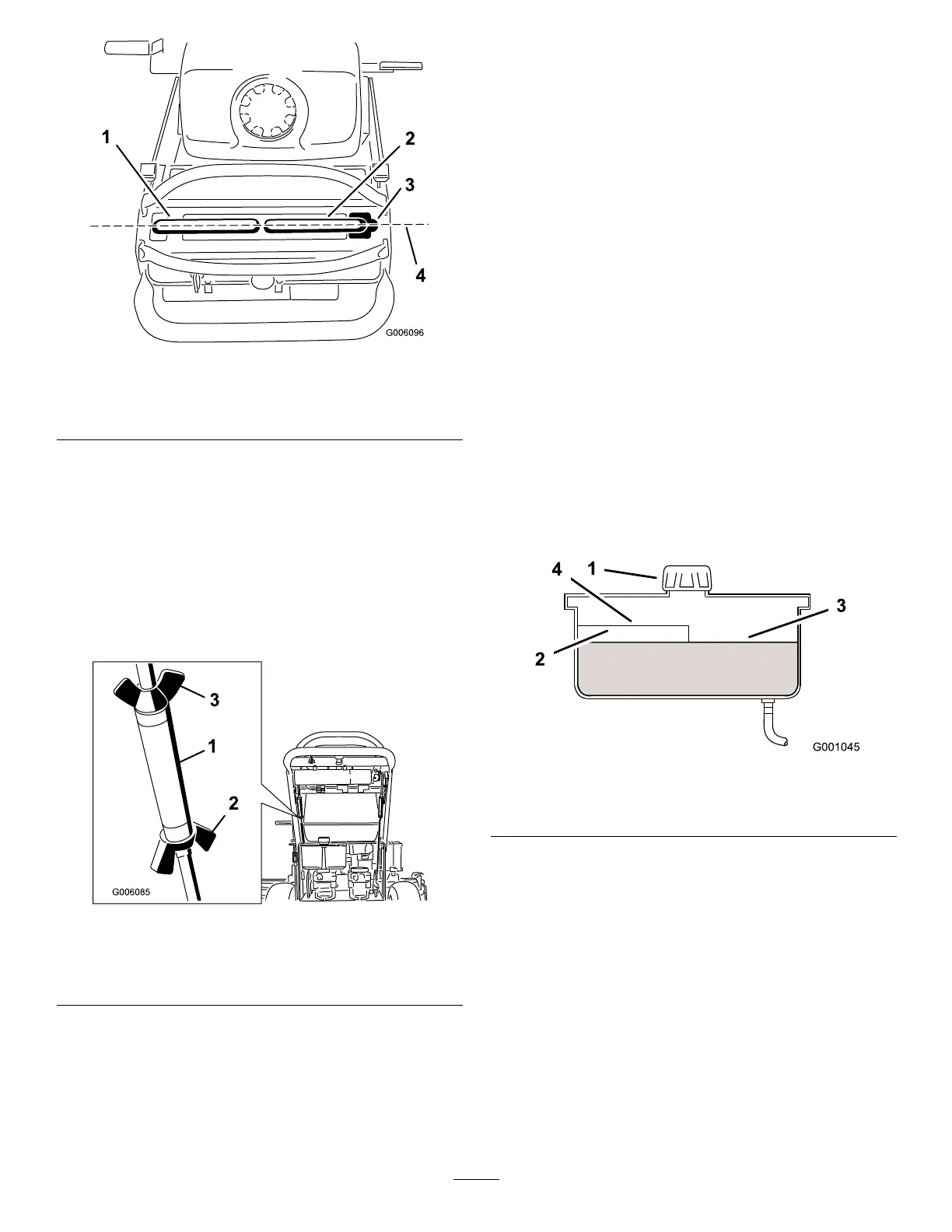
Figure59
1.Cap3.Colduidlevel-full
2.Bafe4.Hotuidlevel-full
5.Removecapfromllerneck.Lookinsidetocheck
theuidlevelinthereservoir.(Figure59).
6.Adduidtothereservoiruntilitreachesthecold
levelofthebafe.
7.Runthemachineatlowidlefor15minutestoallow
anyairtopurgeoutofthesystemandwarmuid.
RefertoStartingandStoppingtheEngine.
8.Rechecktheuidlevelwhiletheuidiswarm.If
required,adduidtothereservoiruntilitreaches
thehotlevelofthebafe.
Note:Theuidlevelshouldbetothetopofthehot
levelofthebafe,whentheuidiswarm(
Figure59).
9.Installcaponllerneck.
42