Setup
MediaandAdditionalParts
Description
Qty.
Use
Operator'sManual
1
Readbeforeoperatingmachine
EngineOperator'sManual
1
Readbeforeoperatingengine
PartsCatalog
1
Usetoreferencepartnumbers
OperatorTrainingMaterial
1
Viewbeforeoperatingmachine
Note:Determinetheleftandrightsidesofthemachinefromthenormaloperatingposition.
AdjustingtheHeight-of-Cut
Important:Thiscuttingdeckoftencutsapproximately
6mm(1/4inch)lowerthanareelcuttingunitwiththe
samebenchsetting.Itmaybenecessarytohavethese
rotarycuttingdeck’sbenchset6mm(1/4inch)above
thatofreelscuttinginthesamearea.
Important:Accesstotherearcuttingunitsisgreatly
improvedbyremovingthecuttingunitfromthetractor.
IftheunitisequippedwithaSidewinder®,sidewindthe
cuttingunitstotheright,removetherearcuttingunit,
andslideitouttotherightside.
1.Lowerthecuttingdecktotheground,stoptheengine,
andremovethekeyfromignitionswitch.
2.Loosentheboltsecuringeachheight-of-cutbracketto
theheight-of-cutplate(frontandeachside)(Figure3).
3.Beginningwithfrontadjustment,removethebolt.
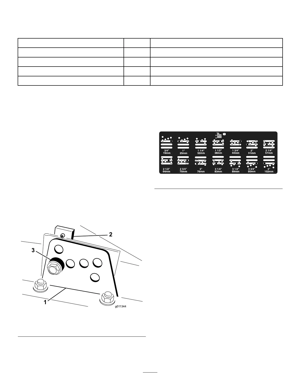
Figure3
1.Heightofcutbracket3.Spacer
2.Heightofcutplate
4.Whilesupportingthechamber,removethespacer
(Figure3).
5.Movethechambertothedesiredheight-of-cutand
installaspacerintothedesignatedheight-of-cuthole
andslot(Figure4).
Figure4
6.Positionthetappedplateinlinewiththespacer.
7.Installtheboltngertight.
8.Repeatsteps4-7foreachsideadjustment.
9.Tightenallthreeboltsto41N-m(30ft-lb).Always
tightenthefrontboltrst.
Note:Adjustmentsofmorethan3.8cm(1-1/2
inches)mayrequiretemporaryassemblytoan
intermediateheighttopreventbinding(e.g.changing
from3.1to7cm(1.25to2.75inch)height-of-cut).
AdjustingtheRollerScraper
(Optional)
Theoptionalrearrollerscraperisdesignedtoworkbest
whenthereisanevengapof0.5to1mm(0.020–0.040inch)
betweenthescraperandroller.
1.Loosenthegreasettingandthemountingscrew
(Figure5).
12