MountingtheCuttingDecksto
theTractionUnit
1.Positionmachineonalevelsurfaceandshutengineoff.
2.Movecuttingdeckintopositioninfrontoftraction
unit.
3.Slidedeckcarrierframeontoliftarmpivotpin.Secure
withlynchpinorretainingnut(GM4700only)(Figure
59).
4.Installthehydraulicmotortothedeck(Figure58).
MakesurethattheO-ringisinpositionandnot
damaged.
5.Greasethespindle.
ServicingtheBladePlane
Therotarydeckcomesfromthefactorypresetat5cm(2.00
inch)height-of-cutandbladerakeof7.9mm(0.310inch).
Theleft-handandright-handheightsarealsopresettowithin
±0.7mm(0.030inch)oftheother.
Thecuttingdeckisdesignedtowithstandbladeimpacts
withoutdeformationofthechamber.Ifasolidobjectis
struck,inspectthebladefordamageandthebladeplanefor
accuracy.
InspectingtheBladePlane
1.Removethehydraulicmotorfromthecuttingdeckand
removethecuttingdeckfromthetractor.
2.Useahoist(orminimumoftwopeople)andplacethe
cuttingdeckonaattable
3.Markoneendofthebladewithapaintpenormarker.
Usethisendofthebladetocheckallheights.
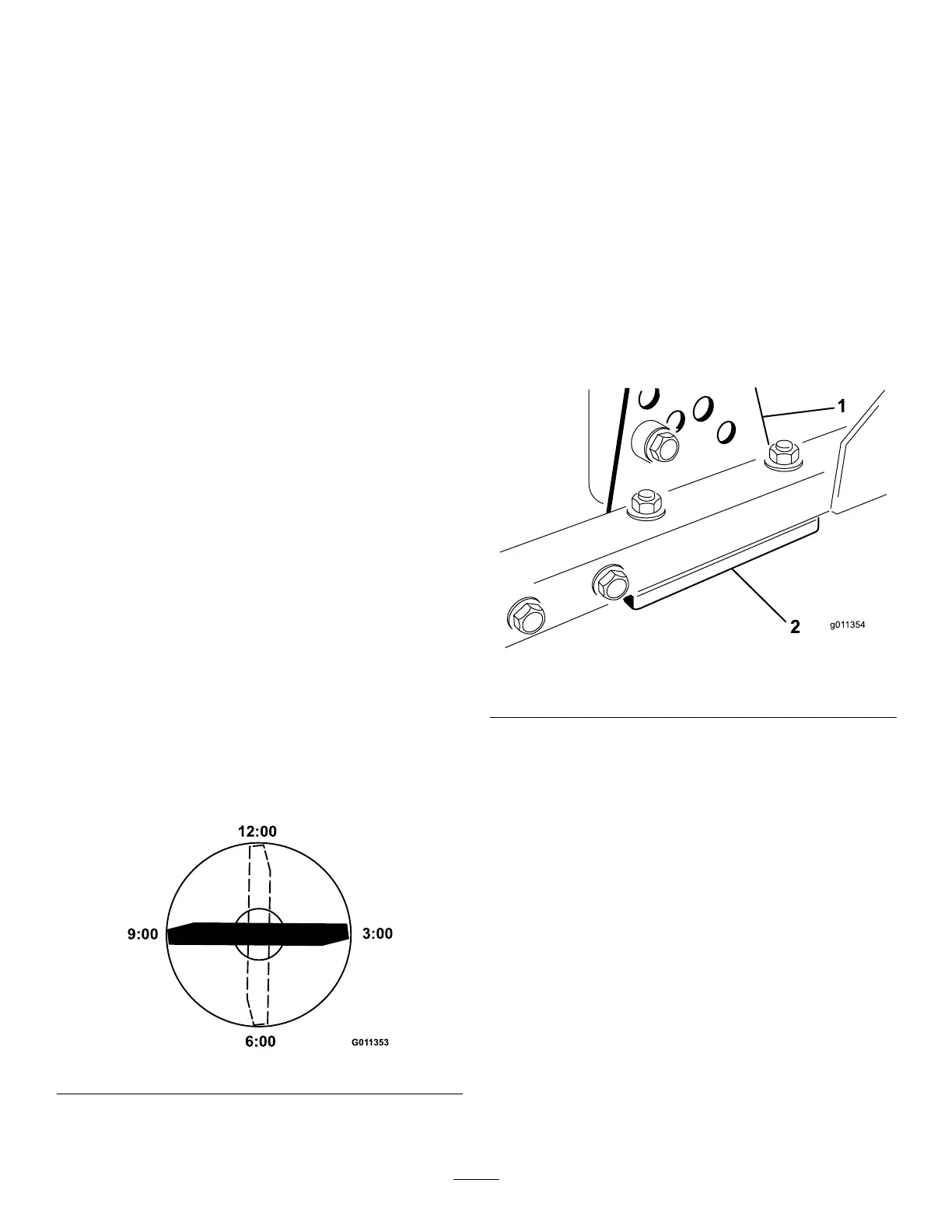
4.Positionthecuttingedgeofthemarkedendofthe
bladeat12o’clock(straightaheadinthedirectionof
mowing)(Figure60)andmeasureheightfromtable
tocuttingedgeofblade.
G01 1353
6:00
12:00
9:00
3:00
Figure60
5.Rotatethemarkedendofthebladetothe3and9
o’clockpositions(Figure60)andmeasuretheheights.
6.Comparethe12o’clockmeasuredheighttothe
height-of-cutsetting.Itshouldbewithin0.7mm(0.030
inch).The3and9o’clockheightsshouldbe3.8±2.2
mm(0.150±.090inch)higherthanthe12o’clock
settingandwithin2.2mm(0.090inch)ofeachother.
Ifanyofthesemeasurementsarenotwithinspecication,
proceedtoAdjustingtheBladePlane.
AdjustingtheBladePlane
Startwiththefrontadjustment(changeonebracketatatime).
1.Removetheheight-of-cutbracket,(front,left,orright)
fromthedeckframe(Figure61).
2.Adjust1.5mm(0.060inch)shimsand/or0.7mm
(0.030inch)shimbetweenthedeckframeandbracket
toachievethedesiredheightsetting(Figure61).
Figure61
1.Heightofcutbracket2.Shims
3.Installtheheight-of-cutbrackettothedeckframewith
theremainingshimsassembledbelowtheheight-of-cut
bracket.
4.Securethesocketheadbolt/spacerandangenut.
Note:Socketheadbolt/spacerareheldtogetherwith
Loctitetopreventthespacerfromfallinginsidethe
deckframe.
5.Verifythe12o’clockheightandadjustifneeded.
6.Determineifonlyoneorboth(right-handand
left-hand)height-of-cutbracketsneedtobeadjusted.
Ifthe3or9o’clocksideis3.8±2.2mm(0.150±0.090
inch)higherthanthenewfrontheightthenno
adjustmentisneededforthatside.Adjusttheother
sidetowithin±2.2mm(0.090inch)ofthecorrectside.
7.Adjusttherightand/orleftheight-of-cutbracketsby
repeatingsteps1through3.
8.Securethecarriageboltsandangenuts.
9.Again,verifythe12,3,and9o’clockheights.
45