InstallingtheCuttingUnits
1.Movethecuttingunitintopositioninfrontofthe
machine.
2.Slidethecuttingunit-carrierframeontothe
lift-arm-pivotpin(Figure79).Securethe
cuttingunittothepinwiththelynchpin(for
Groundsmaster4500machines)orretainingnut
(forGroundsmaster4700machines).
3.Installthehydraulicmotortothecuttingunit
(Figure78).MakesurethattheO-ringisin
positionandnotdamaged.
4.Greasethespindle.
ServicingtheFrontRoller
Inspectthefrontrollerforwear,excesswobble,or
binding.Serviceorreplacetherollerorcomponentsif
anyoftheseconditionsexist.
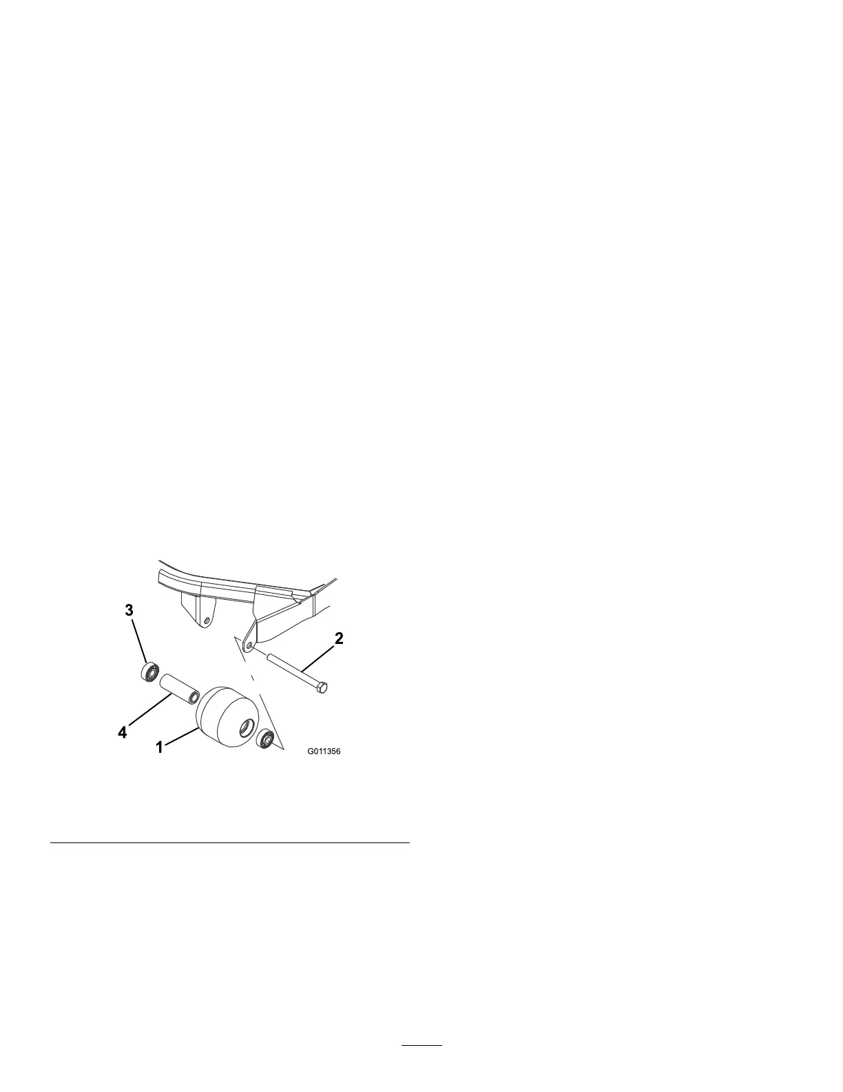
DisassemblingtheFrontRoller
1.Removetheroller-mountingbolt(Figure80).
2.Insertapunchthroughtheendoftheroller
housinganddrivetheoppositebearingoutby
alternatingtapstotheoppositesideofinner
bearingrace.Thereshouldbea1.5mm(0.060
inch)lipofinnerraceexposed.
g011356
Figure80
1.Frontroller3.Bearing
2.Mountingbolt4.Bearingspacer
3.Pushthesecondbearingoutinpress.
4.Inspecttherollerhousing,bearings,andbearing
spacerfordamage(Figure80).Replaceany
damagedcomponentsandassemblethem.
AssemblingtheFrontRoller
1.Presstherstbearingintotherollerhousing
(Figure80).Pressontheouterraceonlyor
equallyontheinnerandouterrace.
2.Insertthespacer(Figure80).
3.Pressthesecondbearingintotherollerhousing
(Figure80).Pressingequallyontheinnerand
outerraceuntiltheinnerracecontactsthe
spacer.
4.Installtherollerassemblyintothecutting-unit
frame.
5.Verifythatthereisnomorethana1.5mm(0.060
inch)gapbetweenrollerassemblyandtheroller
mountbracketsofthecutting-unitframe.Ifthere
isagapover1.5mm(0.060inch),installenough
5/8-inchdiameterwasherstotakeuptheslop.
Important:Securingtherollerassembly
withagaplargerthan1.5mm(0.060inch)
createsasideloadonthebearingandcan
leadtoprematurebearingfailure
6.Torquethemountingboltto108N∙m(80ft-lb).
64