4.Turntheknobclockwise1/4ofaturnatatime.Then
movethespeed-controlforwardandbacktoneutral.
Repeatthisuntiltherightwheelstopsrotatingforward
(Figure41).
5.HoldtheOPCleversdown.
Note:TheOPCleversmustbehelddownwhenever
thespeed-controlleverisoutoftheneutralpositionor
theenginewillstop.
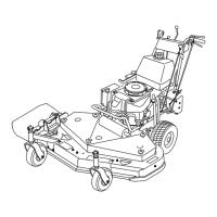
6.Thespringthatkeepstensionontheknobshould
normallynotneedadjustment.Howeverifan
adjustmentisneeded,adjustthelengthofthespringto
26mm(1inch)betweenthewashers(Figure41).
7.Adjustthespringlengthbyturningthenutatthefront
ofspring(Figure41).
Figure41
1.Hydrocontrollinkage
3.Spring
2.Quicktrackknob4.26mm(1inch)
AdjustingtheControlRod
CheckingtheControlRod
1.Withtherearofthemachinestillonjackstandsandthe
enginerunningatfullthrottle,movethespeed-control
levertothemediumspeedposition.
Note:TheOPCleversmustbehelddownwhenever
thespeed-controlleverisoutoftheneutralposition,or
theenginewillstop.
2.Movetherespectivedriveleverupwarduntilitreaches
theneutralpositionandengagetheneutrallocks.
3.Ifthetirerotatesineitherdirection,thelengthofthe
controlrodwillneedtobeadjusted.
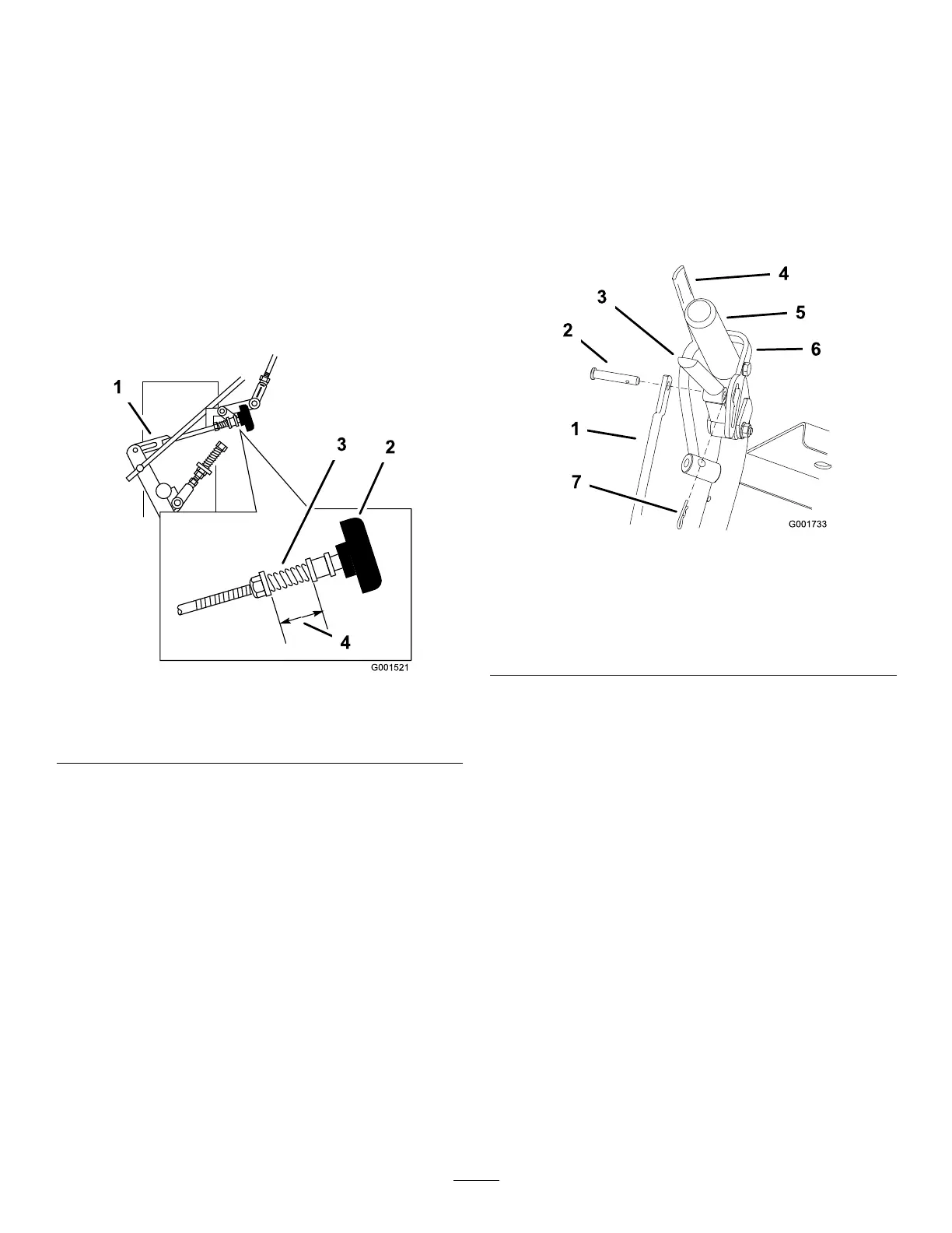
AdjustingtheControlRod
1.Adjusttherodlengthbyreleasingthedriveleverand
removingthehairpincotterpinandclevispin.Rotate
therodintherodtting(Figure42).
2.Lengthenthecontrolrodifthetireisturninginreverse
andshortentherodifthetireisturningforward.
3.Rotatetherodseveralturnsifthetireisrotatingfast.
Then,adjusttherodin1/2turnincrements.
4.Placetheclevispinintothedrivelever(Figure42).
Figure42
1.Controlrod5.Lefthandleshown
2.Clevispin
6.Neutrallock
3.Drivelever7.Hairpincotterpin
4.OperatorPresence
Controllever(OPC)
5.Releaseandengagetheneutrallock,checkingthatthe
tiredoesnotrotate(Figure43).Continuethisprocess
untilthetiredoesnotrotate.
6.Installthehairpincotterpinbetweenthedrivelevers
andtheneutrallocksandintotheclevispins(
Figure
42
).
7.Repeatthisadjustmentfortheoppositeside.
33