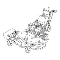
2.Measurefromalevelsurfacetothecuttingedge,
positionA,oftheblades(Figure66).Notethis
dimension.
Figure66
1.Measurefromthecuttingedgetoalevelsurface
3.Rotatetheoppositeendsofthebladesforward.
4.Measurefromalevelsurfacetothecuttingedgeofthe
bladesatthesamepositionasinstep1.Thedifference
betweenthedimensionsobtainedinsteps1and2
mustnotexceed3mm(1/8inch).Ifthisdimension
exceeds3mm(1/8inch),thebladeisbentandmustbe
replaced.RefertoRemovingtheBladesandInstalling
theBlades.
WARNING
Abladethatisbentordamagedcouldbreak
apartandcouldseriouslyinjureorkillyouor
bystanders.
•Alwaysreplacebentordamagedblade
withanewblade.
•Neverleorcreatesharpnotchesinthe
edgesorsurfacesofblade.
RemovingtheBlades
Replacethebladesifyouhitasolidobjectorifthebladesare
outofbalanceorbent.Toensureoptimumperformanceand
continuedsafetyconformanceofthemachine,usegenuine
Tororeplacementblades.Replacementbladesmadebyother
manufacturersmayresultinnon-conformancewithsafety
standards.
1.Holdthebladeboltwithawrench.
2.Removethenut,bladebolt,curvedwasher,blade,
spacers,andthinwasherfromthespindle(Figure67).
Figure67
1.Blade
4.Spacer
2.Bladebolt5.Thinwasher
3.Curvedwasher
6.Nut
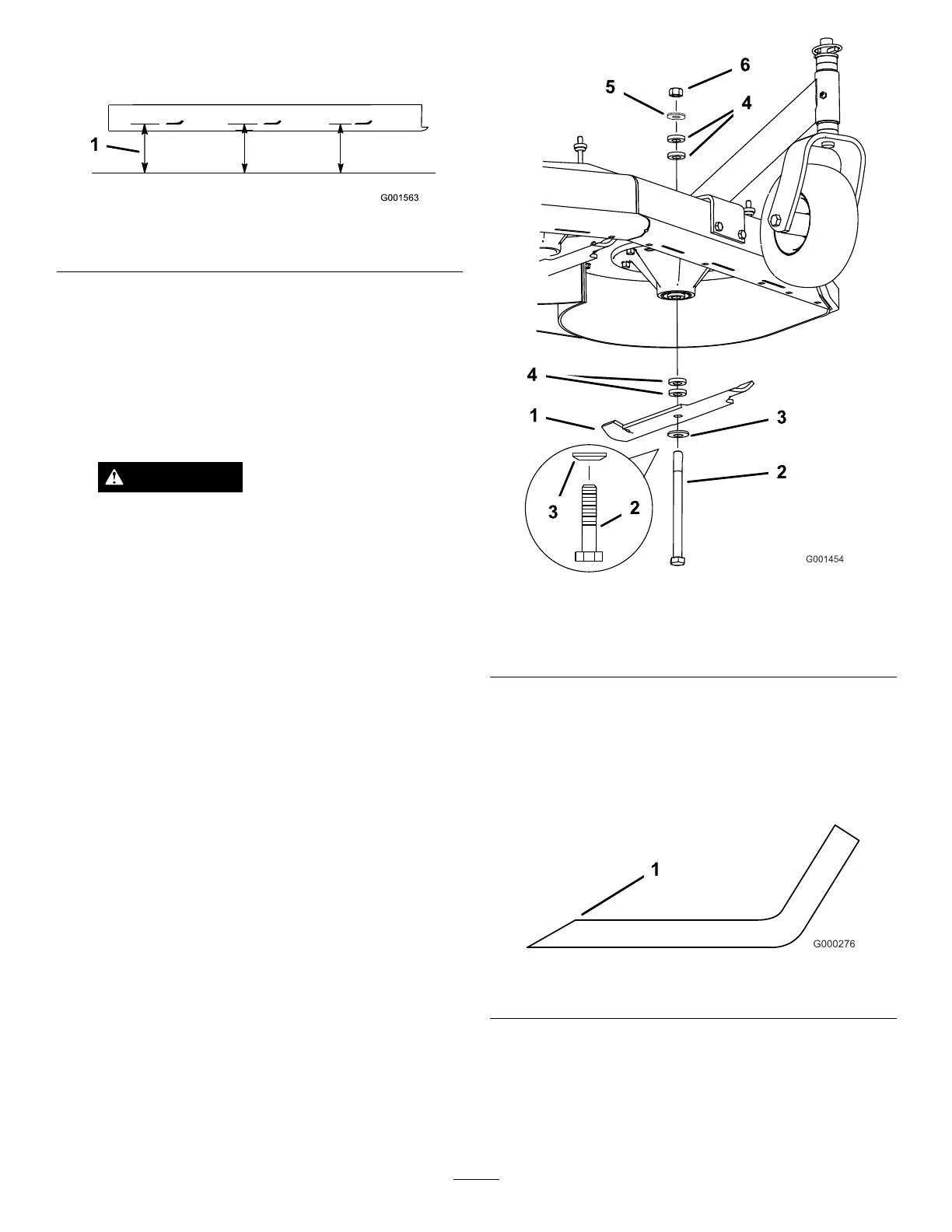
SharpeningtheBlades
1.Usealetosharpenthecuttingedgeatbothendsof
theblade(Figure68).Maintaintheoriginalangle.The
bladeretainsitsbalanceifthesameamountofmaterial
isremovedfrombothcuttingedges.
Figure68
1.Sharpenatoriginalangle
2.Checkthebalanceofthebladebyputtingitonablade
balancer(Figure69).Ifthebladestaysinahorizontal
position,thebladeisbalancedandcanbeused.Ifthe
bladeisnotbalanced,lesomemetalofftheendof
thesailareaonly(Figure69).Repeatthisprocedure
untilthebladeisbalanced.
45