Note:Thepositivebatterycableiswiredtothe
starterorsolenoid.
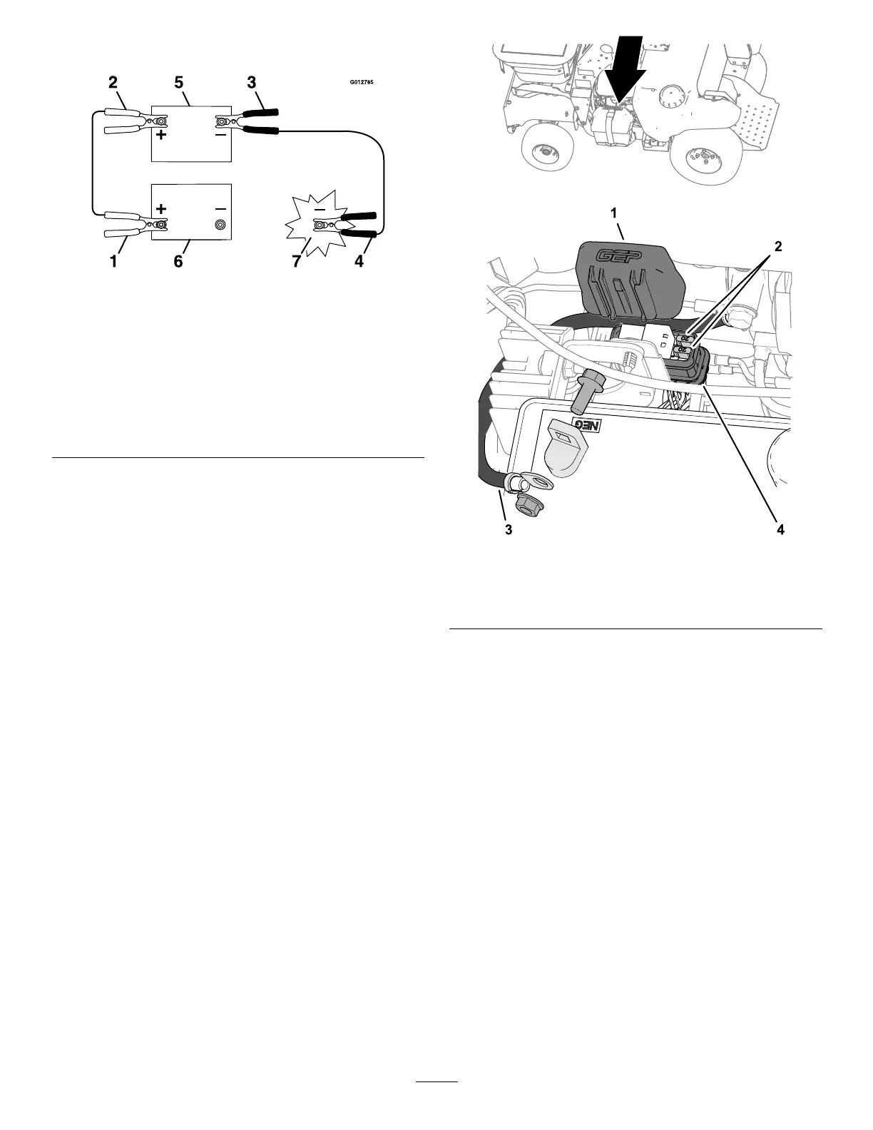
g012785
Figure90
1.Positive(+)cableonthedischargedbattery
2.Positive(+)cableonboosterbattery
3.Negative(–)cableontheboosterbattery
4.Negative(–)cableontheengineblock
5.Boosterbattery
6.Dischargedbattery
7.Engineblock
4.Connecttheotherpositive(+)cableclamp(red)
tothepositiveterminaloftheboosterbattery.
5.Connectthenegative(–)cableclamp(black)to
thenegativeterminaloftheboosterbattery.
6.Connecttheothernegative(–)cableclamp
(black)totheengineblockofthestalledmachine
andawayfromthedischargedbattery.
Important:Donotconnectthenegative(–)
cableclamp(black)tothenegativebattery
postofthedischargedbattery.
7.Standawayfromthedischargedbatteryofthe
machine.
8.Startthemachineandremovethecablesin
thereverseorderofconnection,disconnectthe
engineblockconnectionrst.
ServicingtheFuses
Theelectricalsystemisprotectedbyfuses,and
requiresnomaintenance.Ifafuseblows,checkthe
componentorcircuitforamalfunctionorshort.
1.Removethenegativebatterycablefromthe
batteryterminal;refertosteps2and3of
RemovingtheBattery(page65).
Note:Ensurethatthenegativebatterycable
doesnottouchthebatteryterminal.
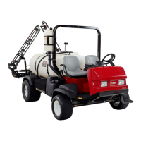
2.Pushthelatchonthefuse/relayholderand
separatethecoverfromtheholder(Figure91).
3.Pullthefusefromthesocketofthefuse/relay
holder(Figure91).
g306403
g304903
Figure91
1.Cover
3.Negativebatterycable
2.Fuses
4.Fuse/relayholder
4.Installafuse(20A)ofthesametypeintothe
socketofthefuse/relayholder(Figure91).
5.Installthecoverontothefuse/relayholderuntil
thecoverlatchessecurely(Figure91).
6.Installthenegativebatterycabletothebattery
terminal,andinstallthebatterycover;referto
steps5and6ofInstallingtheBattery(page66).
67