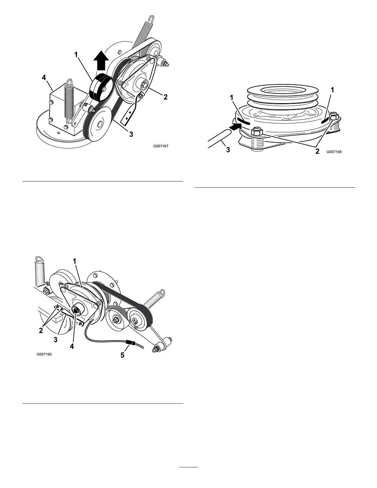
Figure52
1.Springloadedidlerpulley3.PTOdrivebelt
2.Clutch4.Gearbox
6.Unplugtheelectricconnectionfortheclutch
(Figure53).
7.Removethetwoboltsholdingtherubberclutch
straptothemowerframe(Figure53).
8.Removethecenterboltholdingtheclutchto
theengineshaftandremovetheclutchandkey
(Figure53).
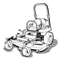
Figure53
1.Clutch4.Clutchcenterbolt
2.Twoboltsandnutsfor
clutchstrap
5.Electricalconnection
3.Rubberclutchstrap
9.Inserta0.015–0.021inch(0.381–0.533mm)feeler
gaugethroughoneinspectionslotinthesideofthe
assembly.Makesureitisbetweenthearmatureand
therotorfrictionsurfaces(Figure54).
10.Tightenthelocknutsuntilthereisslightbindingon
thefeelergaugebutitcanbemovedeasilywithinthe
airgap(Figure54).
11.Repeatthisfortheremainingslots.
12.Checkeachslotagainandmakeslightadjustments
untilthefeelergaugebetweentherotorandarmature
withveryslightcontactbetweenthem.
Figure54
1.Slot
3.Feelergauge
2.Adjustingnut
13.Installtheclutchtotheengineshaftwiththekey.
14.ApplyblueLoctite®(orequivalent)tothecenter
bolt.
15.Whileholdingthecrankshaftatthebackofthe
machine,installthecenterboltandtorqueitto50
ft-lbs(68N-m)(Figure53).
16.Installtherubberclutchstraptothemowerframe
withthetwopreviouslyremovedboltsandnuts
(Figure53).
17.PulluponthespringloadedidlerforthePTOdrive
beltandinstallitontotheclutchpulley(Figure52).
18.Plugintheelectricconnectionfortheclutch
(Figure53).
19.Installthefrontenginepanelandtightentheknobs.
20.Lowerdowntheseat.
42