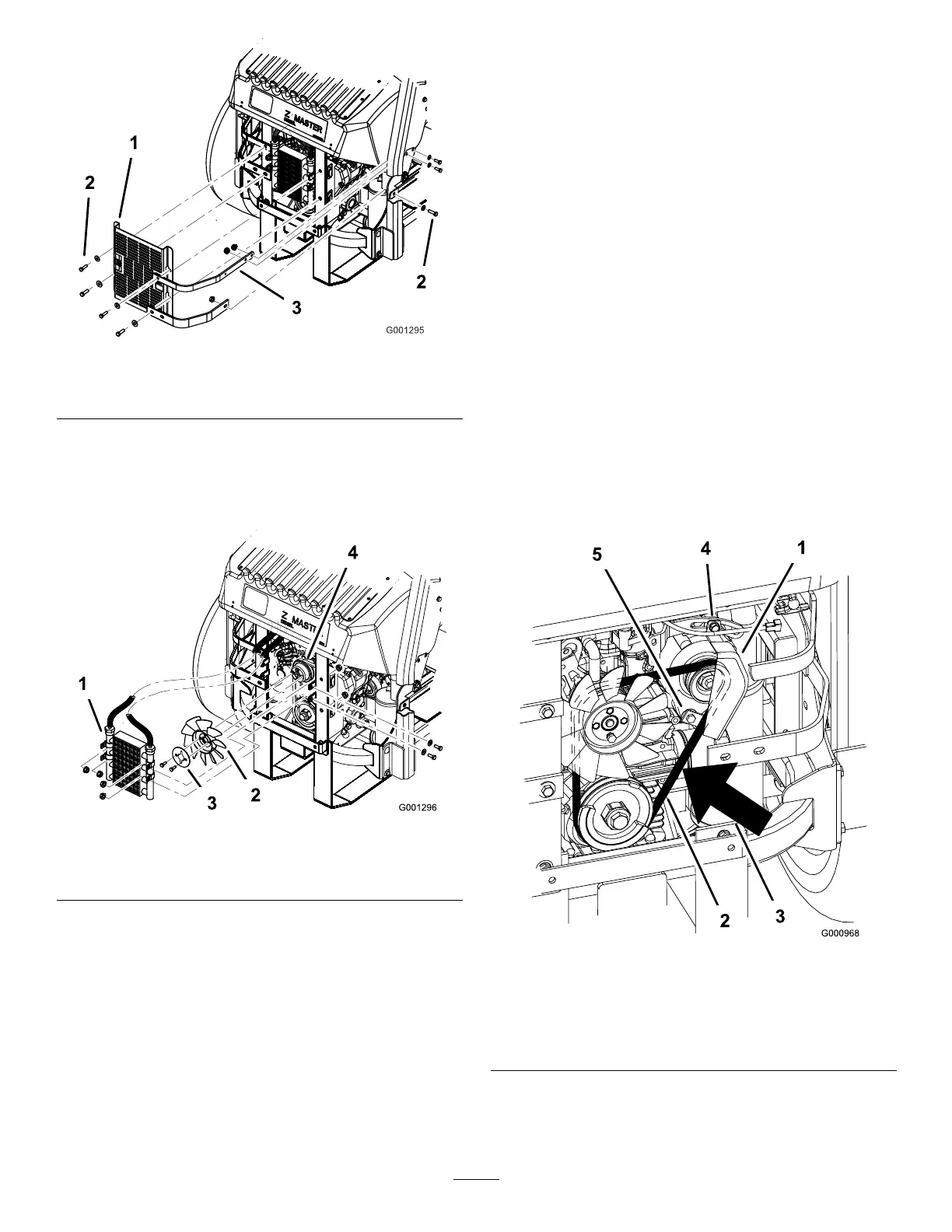
Figure63
1.Oilcoolershield
3.Enginestraps
2.Bolts
5.Removethe4boltsholdingtheoilcoolerand
positiontheoilcoolertotheside(Figure64).
6.Removethe2boltsholdingthefanandfanplateto
themachine(Figure64).
Figure64
1.Oilcooler
3.Fanplate
2.Fan4.Alternatorbelt
7.Loosenthebottomboltandremovetheupperbolt
holdingthealternatorandcover(Figure65).
8.Rotatethealternatorcovertothesideandremove
thebeltfromthepulleysandalternator.
9.Installanewbeltaroundthepulleysandthe
alternator(Figure65).
10.Installthefanandfanplatetothemachinewiththe
2boltspreviouslyremoved(Figure64).
11.Installtheoilcoolerwiththe4boltspreviously
removed(Figure64).
12.Installtheoilcoolershieldandenginestrapsto
therearframewiththe4boltspreviouslyremoved
(Figure63).
13.Installtheenginestrapstothesideofthemachine
(Figure63).
14.Tightenthebottomboltandinstalltheupperbolt
holdingthealternatorandcover(Figure65).
TensioningtheAlternatorBelt
1.Placeahandlebetweenthealternatorandcylinder
block.
2.Adjustthealternatortotheoutsideuntilthereis
1/4to11/32inch(7to9mm)deectioninthebelt
betweentheengineandthealternatorpulleyswith
22.1lbsofforce(10kgf)(Figure65).
3.Tightenthealternatorbolts.
4.Checkthedeectioninthebeltagainandadjustthe
beltifneeded.
5.Ifthedeectioniscorrect,tightenthebottomand
upperbolt(Figure65).
Figure65
1.Alternator4.Topbolt
2.Alternatorbelt5.Bottombolt
3.Deection,1/4to
11/32inch(7to9mm)with
22.1lbsofforce(10kgf)
47