Operation
Note:Determinetheleftandrightsidesofthe
machinefromthenormaloperatingposition.
CAUTION
Ifyouleavethekeyintheignitionswitch,
someonecouldaccidentlystarttheengine
andseriouslyinjureyouorotherbystanders.
Removethekeyfromtheignitionbeforeyou
doanymaintenance.
AdjustingtheHeightofCut
Theheightofcutcanbeadjustedfrom25to127mm
(1to5inches)in6mm(1/4inch)increments.
CenterDeck
Theheightofcutonthecenterdeckisachievedby
movingthestoppinintodifferentholelocations.
1.Withtheenginerunning,pushbackonthe
mowerliftswitchuntilthemowerisfullyraised
andreleasetheswitchimmediately.
2.Toadjust,rotatethestoppinuntilthenubon
itlinesupwiththeslotsintheholesinthe
height-of-cutbracketandremoveit(Figure4).
g025272
Figure4
1.Stoppin
3.Selectaholeintheheight-of-cutbracket
correspondingtotheheightofcutdesired,insert
thepin,androtateitdowntolockitinplace
(Figure4).
Note:Thereare4rowsofholepositions(Figure
4).Thetoprowgivesyoutheheightofcutlisted
abovethepin.Thesecondrowdowngivesyou
theheightlistedplus6mm(1/4inch).Thethird
rowdowngivesyoutheheightlistedplus12mm
(1/2inch).Thebottomrowgivesyoutheheight
listedplus18mm(3/4inch).Forthe127mm(5
inch)positionthereisonlyonehole,locatedin
thesecondrow.Thisdoesnotadd6mm(1/4
inch)tothe127mm(5inch)position.
4.Adjusttheanti-scalprollersandskidsas
required.
WingDecks
Theheightofcutonthewingdecksisachievedby
positioningthecasterwheelaxlesintheupperor
lowerholesofthecasterforks,addorremovean
equalnumberofspacersfromthecasterforksand
securetheheight-of-cutcollartothedesiredholesin
theheight-of-cutrod.
1.Starttheengineandraisethecuttingunitoffthe
oorsothattheheightofcutcanbechanged.
Stoptheengineandremovethekeyafterthe
cuttingunitisraised.
2.Positionthecasterwheelaxlesinthesame
holesinbothcasterforks.RefertoFigure5to
determinethecorrectholesforthesetting.
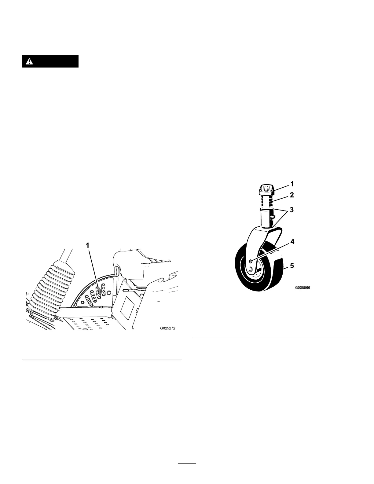
g008866
Figure5
1.Tensioningcap4.Axlemountingholes
2.Spacers5.Casterwheel
3.Shims
Note:Whenoperatingina64mm(2-1/2inch)
cuttingheightorhigher,theaxleboltmustbe
installedinthelowercasterforkholetoprevent
grassbuildupbetweenthewheelandthefork.
Whenoperatinginacuttingheightlowerthan64
mm(2-1/2inch)andgrassbuildupisdetected,
reversethemachinesdirectiontopullany
clippingsawayfromthewheel/forkarea.
3.Removethetensioningcapfromthespindle
shaft(Figure5)andslidethespindleoutofthe
casterarm.Putthe2shims(1/8inch)ontothe
spindleshaftastheywereoriginallyinstalled.
Theseshimsarerequiredtoachievealevel
acrosstheentirewidthofthecuttingunits.Slide
10

 Loading...