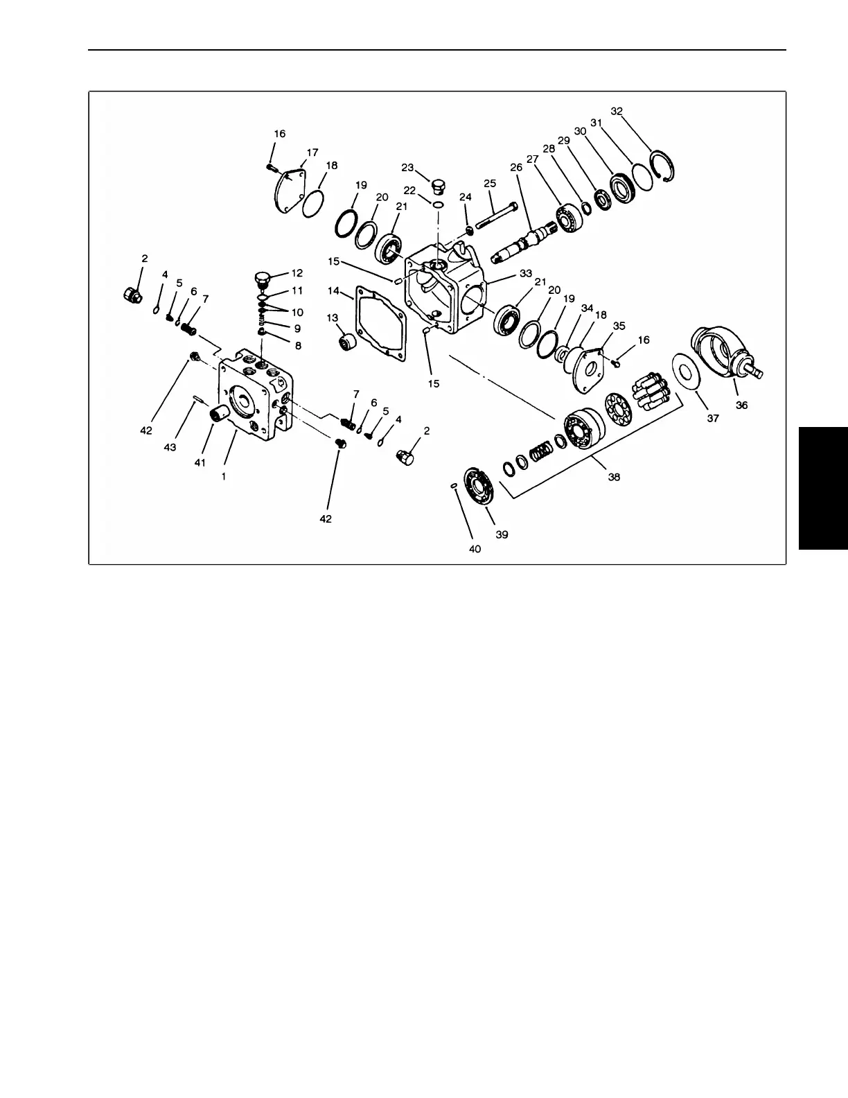
Traction Pump Charge Pressure Relief Valve (Fig. 20)
Hydraulic System
Figure 20
1. Park the machine on a level surface, lower cutting
units, en
gage parking brake and stop the engine.
2. Remove the charge relief valve hex plug (Item 12).
3. Remove the spring (Item 9) and poppet (Item 8) from
the
housing.
4. Do not interchange parts with another valve.
NOTE: The shim(s) (Item 10) which may be installed
betwe
en the spring and plug may remain inside the plug,
being held by an oil film. Make sure the same number
and thickness of shims is installed when reassembling
the parts unless shims need to be added or removed to
a
djust the pressure setting.
5. Inspect the poppet and mating seat in the end cap for
damage or foreign material.
6. Reinstall the poppet, spring and plug (with shims and
o-ring) into the housing. Tighten the plug to a torque of
30 to 70 ft-lb.
7. Before starting the engine check the oil level in the
dif
ferential housing and add the correct oil as necessary.
Start the engine and let it run for one to two minutes,
then turn the engine off and check the oil level again.
Check the transmission for leaks.
Groundsmaster
®
455-D Page 4 - 31 Repairs

 Loading...


