Wing Switch Replacement
1. Park machine on a level surface, engage parking
brake, lower the cutting units and turn engine OFF.
2. Remove deck covers.
3. Disconnect wing switch electrical connector.
4. Remove boot, spring, nut and washer, then remove
the wing sw
itch. Disconnect wiring assembly from
switch terminals.
5. Install wire assembly on new wing switch. Make sure
t
hat one wire is connected to the “COMMON” terminal,
and one wire is connected to the “NORMALLY OPEN”
(N.O.) terminal.
IMPORTANT: The wing switch has three (3) termi-
nals. I
f the two (2) wires are not connected to the
“COMMON” and “NORMALLY OPEN” (N.O.) termi-
nals, the safety interlock circuit will not function
properly.
If the wires are not correctly installed to the
switch, the wing deck could operate when in
the raised position.
CAUTION
6. Coat switch terminals and wires with skin-over
grease.
7. Install new switch. Apply Loctite 242 or equivalent
s
witch threads before installing nut. Tighten nut to a
torque of 75 - 100 in-lb. Install spring and boot.
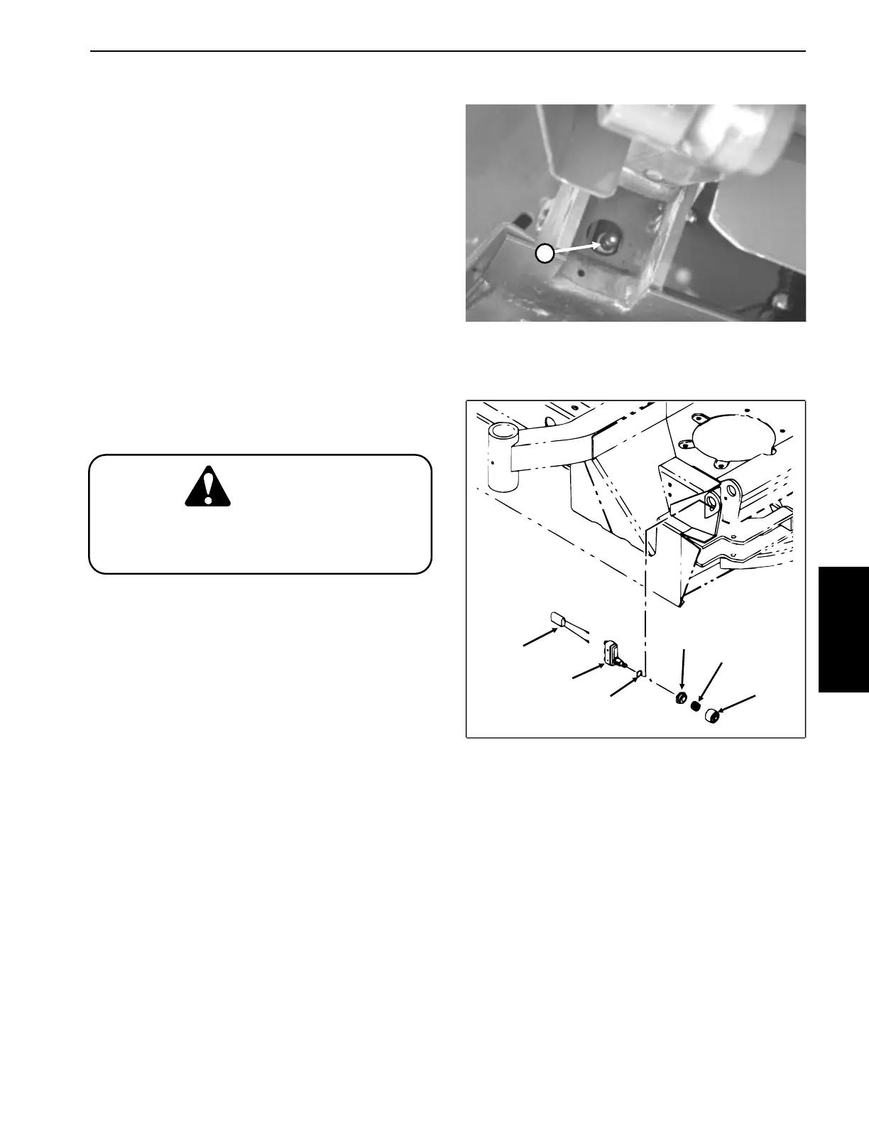
Figure 38
1. Wing switch
(Shown from below wing with wing in raised position)
4
1
5
2
3
Figure 39
1. Wire assembly 4. Nut
2.Wing switch 5. Spring
3. Washer 6. Boot
Electrical System
Groundsmaster
®
455-D Page 5 - 33 Repairs
6

 Loading...


