Groundsmaster 4300--D Hydraulic SystemPage 4 -- 75
IMPORTANT: Markthe relative positions ofthegear
teeth and the thrust plates so they can be reassem-
bledinthesameposition.Donottouchthegearsur-
faces as residueon handsmay be corrosiveto gear
finish.
7. Removethe thrustplatesand sealsfromeachpump
section. Before removing each gear set, apply marking
dye to mating teeth to retain ”timing”. Pump efficiency
maybeaffectedif theteetharenot installedinthesame
positionduringassembly.Keepthepartsforeachpump
section together; do not mix parts between sections.
8. Clean all parts. Check all components for burrs,
scoring, nicks and other damage.
9. Replace the entire pump assembly if parts are ex-
cessively worn or scored.
Disassembly (Fig. 72)
1. Apply clean hydraulic oil to all parts before assem-
bling.
NOTE: Pressuresealsandback--upringsfitingrooves
machined into thrust plates. Body seals fit in grooves
machined in body faces.
2. Assemble pumpsections startingatfront coverend.
Apply grease or petroleum jelly to new section seals to
hold them in position during gear pump assembly.
3. Afterpumphasbeenassembled,tightencapscrews
and nuts by hand. Rotate the drive shaft to check for
binding. Protect the shaft if using a pliers.
4. Tightenthecapscrewsandnutsevenlyinacrossing
pattern to a torque of 33 ft--lb (45 N--m).
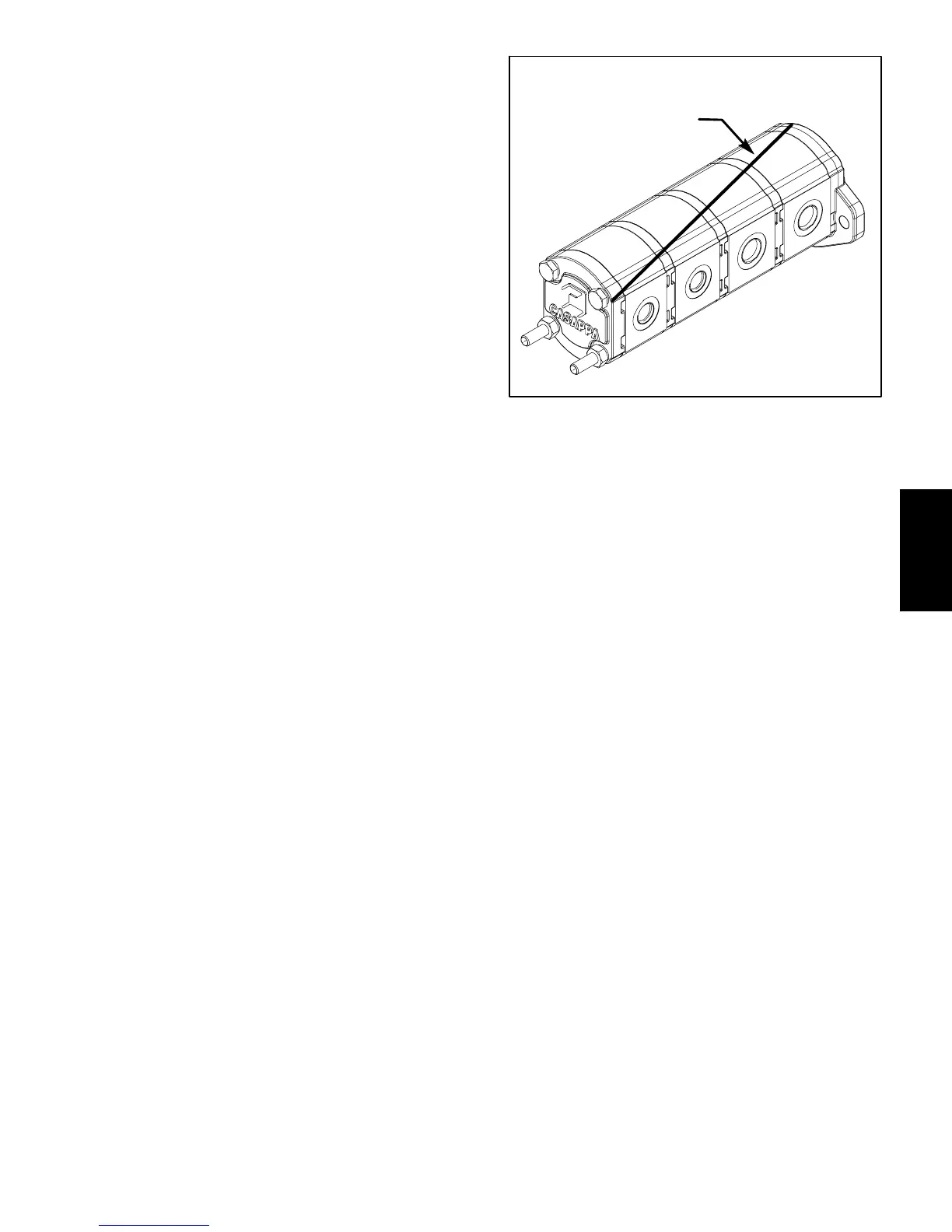
Figure 73
DIAGONAL LINE
Hydraulic
System

 Loading...


