Groundsmaster 4300--DPage 5 -- 32Electrical System
Start Relay
The start relay is used in the engine starting circuit.
When energized by the TEC controller, the start relay
provides a current path to energize the engine starter
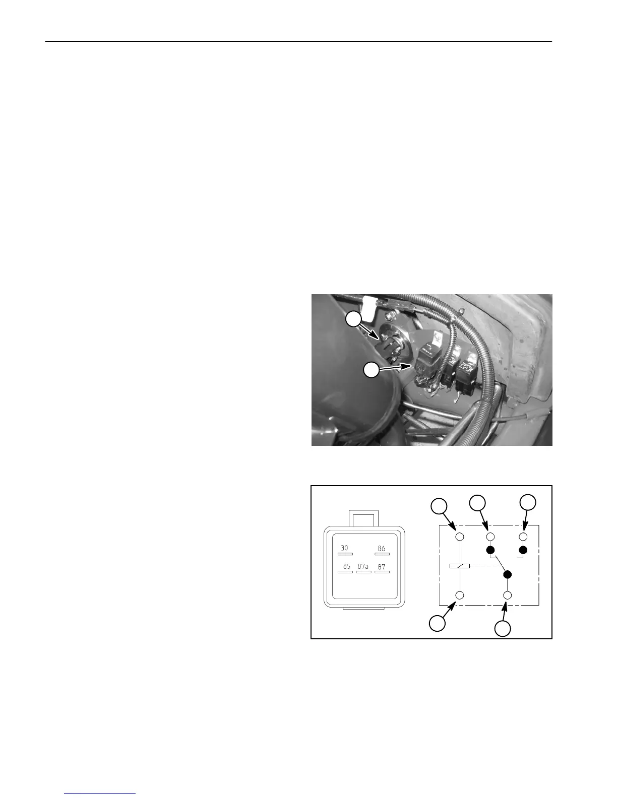
solenoid. The start relay is attached to a frame bracket
under the hood next to the hydraulic pump drive shaft
(Fig. 34).
The TEC controllercontrols and monitors theoperation
of the start relay. The relay and its circuit wiring should
be tested asa controller output withthe Diagnostic Dis-
play before disconnecting and testing the relay (see
DiagnosticDisplayintheTroubleshootingsectionofthis
chapter). If the controller has detected a malfunction in
thestartrelaycircuit,the Diagnosticlight canbe usedto
identify the fault (see D iagnostic Light in the Trouble-
shooting section of this chapter).
Testing
1. Before disconnecting the start relay for testing, test
relayanditscircuitwiringasaTECcontrolleroutputwith
the Diagnostic Display (see Diagnostic D isplay in the
Troubleshootingsectionof thischapter).Ifthe Diagnos-
tic Display verifies that the relay and circuit wiring are
functioning correctly, no further relay testing is neces-
sary.
2. If the Diagnostic Display determines that start relay
andcircuitwiringarenotfunctioningcorrectly,parkma-
chine on a level surface, lower cutting decks, stop en-
gine, apply parking brake and remove key from ignition
switch. Open hood to gain access to relay.
3. Locate start relay and disconnect the machine wire
harness connector from the relay. Remove relay from
machine for easier testing.
NOTE: Prior to taking small resistance readings with a
digital multimeter, short the meter test leads together.
The meter will display a small resistance value (usually
0.5 ohms or less). This resistance is due to the internal
resistanceofthe meterandtestleads.Subtractthisval-
ue from the measured value of the component you are
testing.
4. Using a multimeter (ohms setting), measure c oil re-
sistancebetween terminals 85and 86(Fig. 35). Resist-
ance should be between 70 and 90 ohms.
5. Connectmultimeter(ohmss etting)leadstorelayter-
minals 30 and 87. Ground terminal 86 and apply +12
VDC to terminal 85. The relay terminals 30 and 87
shouldhavecontinuityas+12VDCisappliedtoterminal
85.Therelayterminals30and87shouldnothaveconti-
nuity as +12 VDC is removed from terminal 85.
6. Disconnect voltage from terminal85 and multimeter
lead from terminal 87.
7. Connectmultimeter(ohmss etting)leadstorelayter-
minals 30 and 87A. With terminal 86 grounded, apply
+12VDCtoterminal85.Therelayterminals30and87A
shouldnot havecontinuity as+12 VDCisappliedtoter-
minal 85. The relay terminals 30 and 87A should have
continuity as +12 VDC is removed from terminal 85.
8. When testing is completed, disconnect voltage and
multimeterleadsfromtherelayterminals.Replacerelay
if necessary.
9. Secure relay to machine and connect machine wire
harness connector to r elay.
10.Lower and secure hood.
Figure 34
1. Pump drive shaft 2. Start relay
2
1
Figure 35
86
85
87A 87
30
2
1
3
4
1. Coil terminal
2. Common terminal
3. Normally closed term.
4. Normally open term.
1

 Loading...


