Groundsmaster 4300--DHydraulic System Page 4 -- 92
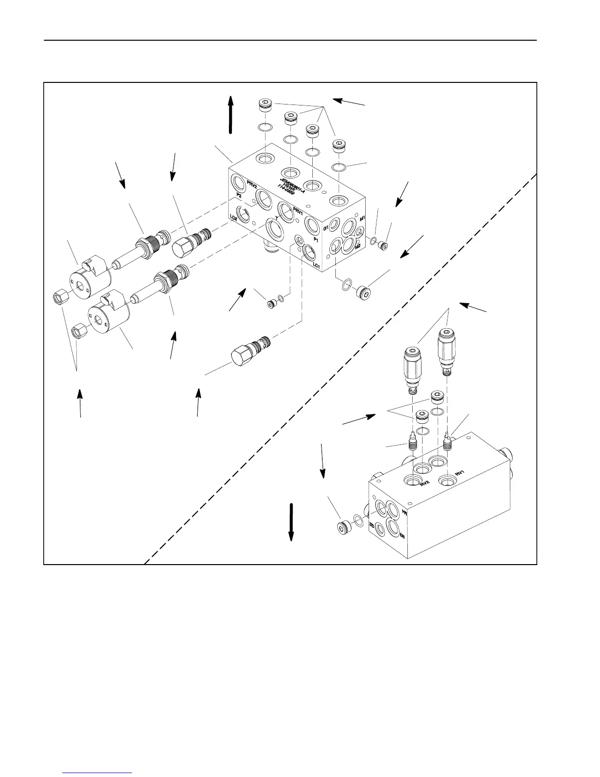
Deck Control Manifold Service
1. Deck control manifold
2. Logic element (LC1/LC2)
3. Proportional relief valve (PRV1/PRV2)
4. Solenoid coil
5. Nut
6. Plug (zero leak #4)
7. O--ring
8. Plug (zero leak #8)
9. O--ring
10. Relief valve (RV1/RV2)
11. Pilot piston
Figure 81
2
3
6
8
9
1
5
7
4
2
3
4
6
8
10
11
8
11
8
60 in--lb
(6.7 N--m)
25 ft--lb
(33 N--m)
35 ft--lb
(47 N--m)
20 ft--lb
(27 N--m)
UP
35 ft--lb
(47 N--m)
25 ft--lb
(33 N--m)
50 ft--lb
(68 N--m)
20 ft--lb
(27 N--m)
50 ft--lb
(68 N--m)
UP
20 ft--lb
(27 N--m)
50 ft--lb
(68 N--m)
NOTE: The ports on the deck control manifold are
markedforeasyidentificationofcomponents.Example:
P1isthepumpP1connectionportandPRV2istheloca-
tionfortheproportionalreliefvalvePRV2(seeHydraulic
Schematic in Chapter 8 -- Foldout Drawings to identify
the function of the hydraulic lines and cartridge valves
at each manifold port).

 Loading...


