Groundsmaster 4300--D Hydraulic SystemPage 4 -- 101
WARNING
Make sure that cutting decks are fully lowered
before loosening hydraulic lines, cartridge
valves or plugs from lift control manifold. If
decks are not fully lowered as manifold compo-
nents are loosened, decks may drop unexpect-
edly.
5. Disconnect hydraulichoses and linesfrom fittingsin
manifold. Allow lines to drain into a suitable container.
Remove and discard O--rings.
6. Put caps or plugs on disconnected lines and fittings
to prevent contamination.
7. Label all solenoid coil wire harness leads for as-
semblypurposes.Unplugwireharnessleadsfromsole-
noid coils on manifold.
8. Remove two (2) flange head screws that secure
manifold to machine frame.
9. Remove lift control manifold from machine.
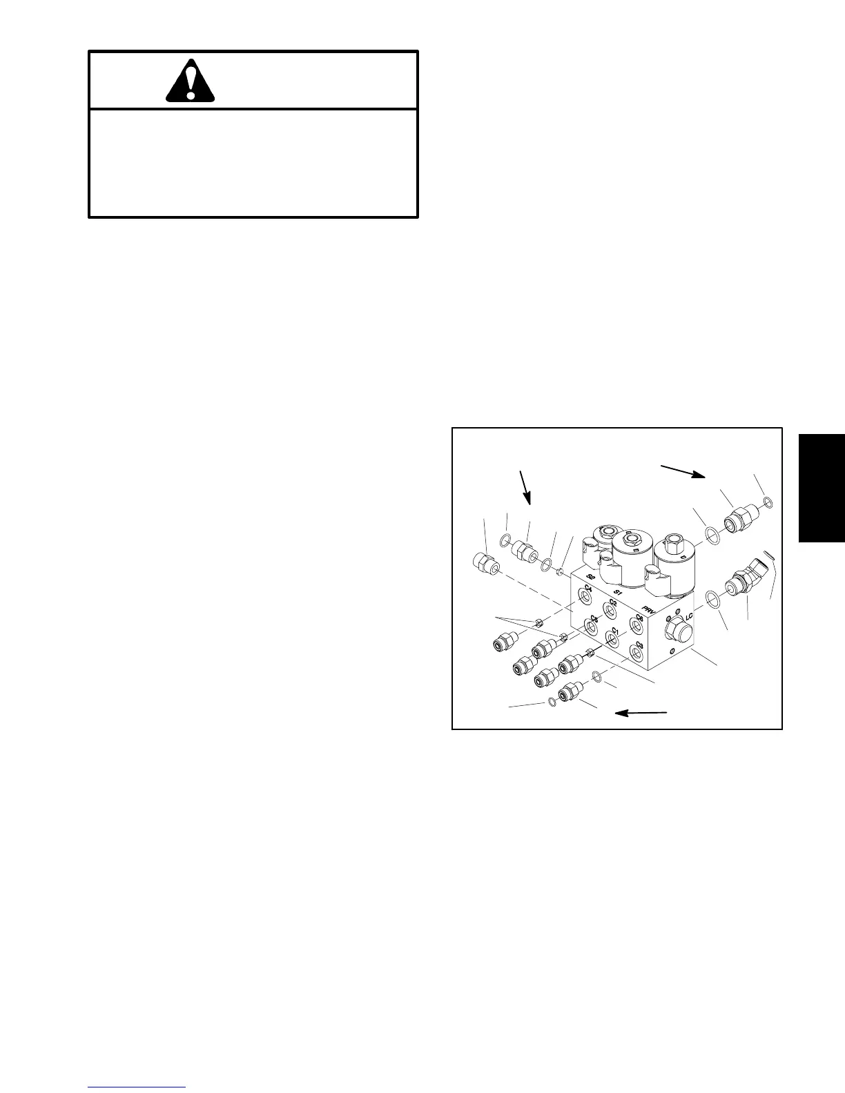
IMPORTANT: A flow control orifice is placed be-
neath several hydraulic fittings on the lift control
manifold (Fig. 91). The lift manifold uses two (2) dif-
ferentorificesizes.Iffittingsareremovedfromman-
ifoldandanorificeisinthemanifoldport,makesure
toremoveorifice and label itspositionforassembly
purposes.
10.Ifnecessary,remove hydraulicfittingsfrommanifold
(Fig. 91). Discard any removed O--rings. Locate, re-
trieve and label orifice from manifold port (if equipped).
Installation (Fig. 90)
1. If fittings were removed from manifold (Fig. 91):
A. Lubricate new O--rings with clean hydraulic oil.
Install lubricated O--rings on fittings.
IMPORTANT: Wheninstallingorificeinmanifold,
make sure that orifice is flat in the base of the fit-
ting cavity. Manifold damage is possible if the
orifice is cocked in the cavity.
B. For manifold ports with orifice, place correct ori-
fice in port with the orifice slot facing out.
C. Install fittings into manifold. Torque fittings to
torque values identified in Figure 91.
2. Position lift control manifold to frame. Install two (2)
flange head screws but do not fully tighten.
3. Remove caps and plugs from disconnected lines
and fittings.
4. Lubricate and install new O--ring(s) on manifold fit-
tings. Connect hydraulic lines to hydraulic manifold fit-
tingsandproperlytightenallconnections(seeHydraulic
Hose and Tube Installation in the General Information
section of this chapter).
5. Securehydraulicmanifoldtoframebytighteningtwo
(2) flange head screws.
6. Connect wire harness leads to solenoid coils on
manifold using labels placed during removal.
7. Checkoillevel inhydraulicreservoirandaddcorrect
oil if necessary.
8. Follow Hydraulic System Start--up procedures (see
Hydraulic System Start--up in this section).
1. Lift control manifold
2. Straight fitting (2 used)
3. O--ring
4. O--ring
5. Orifice (0.030)
6. Orifice (0.046) (3 used)
7. Straight fitting (6 used)
8. O--ring
9. O--ring
10. Straight fitting
11. 45
o
fitting
12. O--ring
Figure 91
(68 N--m)
50 ft--lb
(27 N--m)
20 ft--lb
(27 N--m)
20 ft--lb
1
5
3
4
7
6
2
6
2
3
4
9
8
9
11
12
10
Hydraulic
System

 Loading...


