Groundsmaster 4300--D Hydraulic SystemPage 4 -- 109
CAUTION
Beforeopeninghydraulicsystem,operateallhy-
draulic controls to relieve system pressure and
avoid injury from pressurized hydraulic oil. See
RelievingHydraulicSystemPressurein theGen-
eral Information section of this chapter.
7. Disconnect hydraulic lines from steering control
valve. Allow lines to drain into a suitable container.
8. Put caps or plugs on disconnected lines and fittings
to prevent contamination.
9. Loosen and remove remaining two (2) socket head
screws and flange nuts that secure steering column to
machine.
10.Remove steering column and steering control valve
assembly from machine.
11.Loosenandremovefour(4)socketheadscrewsthat
secure steering control valve to steering column.
12.Remove steering control valve from steering col-
umn.
13.Ifnecessary,removefittingsandO--ringsfromsteer-
ing control valve. Discard all removed O--rings.
Installation (Fig. 97)
1. If fittings were removed, lubricate new O--rings with
clean hydraulic oil and install fittings to steering control
valve (see Hydraulic Fitting Installation in the General
Information section of this chapter).
2. Apply antiseize lubricant to splines of steering con-
trol valve shaft.
3. Slide steering control valve shaft into steering col-
umn universal joint. Position control valve withportsto-
ward front of machine. Secure steering control valve to
steering c olumn with four (4) socket head screws.
Torque screws in a criss--cross pattern from 84 to 120
in--lb (9.5 to 13.5 N--m).
4. Position steering column assembly to machine. Se-
cure steering column in place with two (2) socket head
screws and flange nuts at rear two mounting holes.
5. Remove caps and plugs from disconnected lines
and fittings.
6. Lubricate new O--rings and connect hydraulic lines
tofittingsonsteeringcontrolvalve.Tightenconnections
(seeHydraulicHoseandTube InstallationintheGener-
al Information section of this chapter).
7. Position steeringcolumnbrace(item 13)tomachine
and secure with four (4) screws and flange nuts.
8. Slide rubber bellows to bottom of steering column.
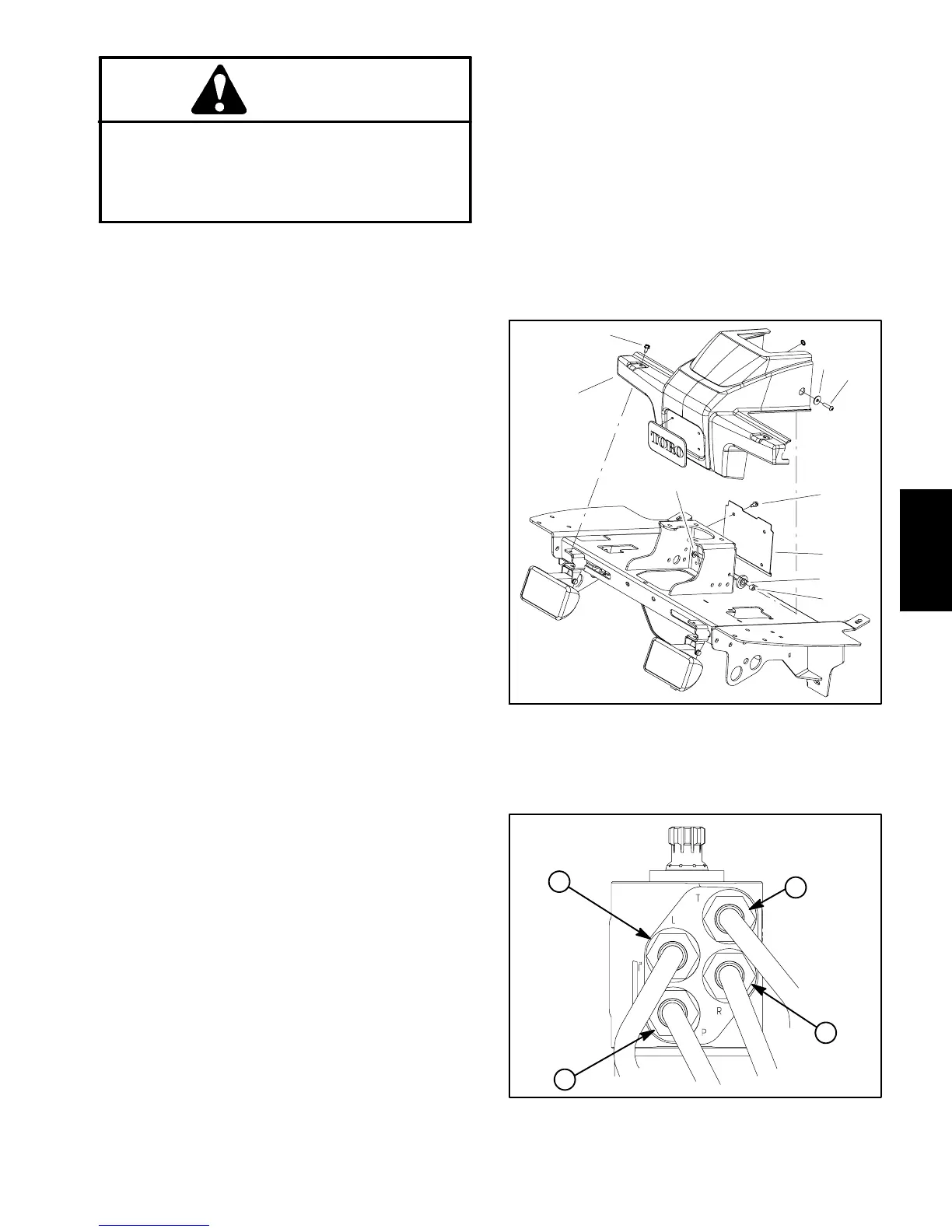
9. Place r ubber bushings and spacers into holes of
shroud (Fig. 98). Position shroud in place and secure
with removed fasteners.
10.Checkoillevel inhydraulicreservoirandaddcorrect
oil if necessary.
11.Follow H ydraulic System Start--up procedures (see
Hydraulic System Start--up in this section).
1. Washer (2 used)
2. Screw (2 used)
3. Washer head screw
4. Platform shroud
5. Lock nut (2 used)
6. Cover plate
7. Bushing (2 used)
8. Spacer (2 used)
Figure 98
3
4
1
2
5
3
6
7
8
Figure 99
L
P
R
T
Hydraulic
System

 Loading...


