Groundsmaster 4300--D Hydraulic SystemPage 4 -- 113
Removal (Fig. 101)
1. Park the machine on a level surface, engage the
parking brake, lower the cutting decks and stop the en-
gine. Remove the key from the ignition switch.
2. Read the General Precautions for R emoving and
Installing Hydraulic System Components at the begin-
ning of the Service and Repairs section of this chapter.
CAUTION
Beforeopeninghydraulicsystem,operateallhy-
draulic controls to relieve system pressure and
avoid injury from pressurized hydraulic oil. See
RelievingHydraulicSystemPressurein theGen-
eral Information section of this chapter.
3. Label all hydraulic connections for assembly pur-
poses. Thoroughly clean hydraulic hose ends prior to
disconnecting hoses from the steering cylinder.
4. Disconnect hydraulic hoses from steering cylinder.
5. Putcapsorplugsondisconnectedhosesandfittings
to prevent contamination.
6. Removetwo(2)jamnuts(item16)thatsecuresteer-
ing cylinder to axle. Remove cotter pin (item 20) and
slottedhex nut(item29) thatsecuresteering cylinderto
RH drag link.
7. Separate s teering cylinder ball joints from axle as-
sembly and remove steering cylinder from machine.
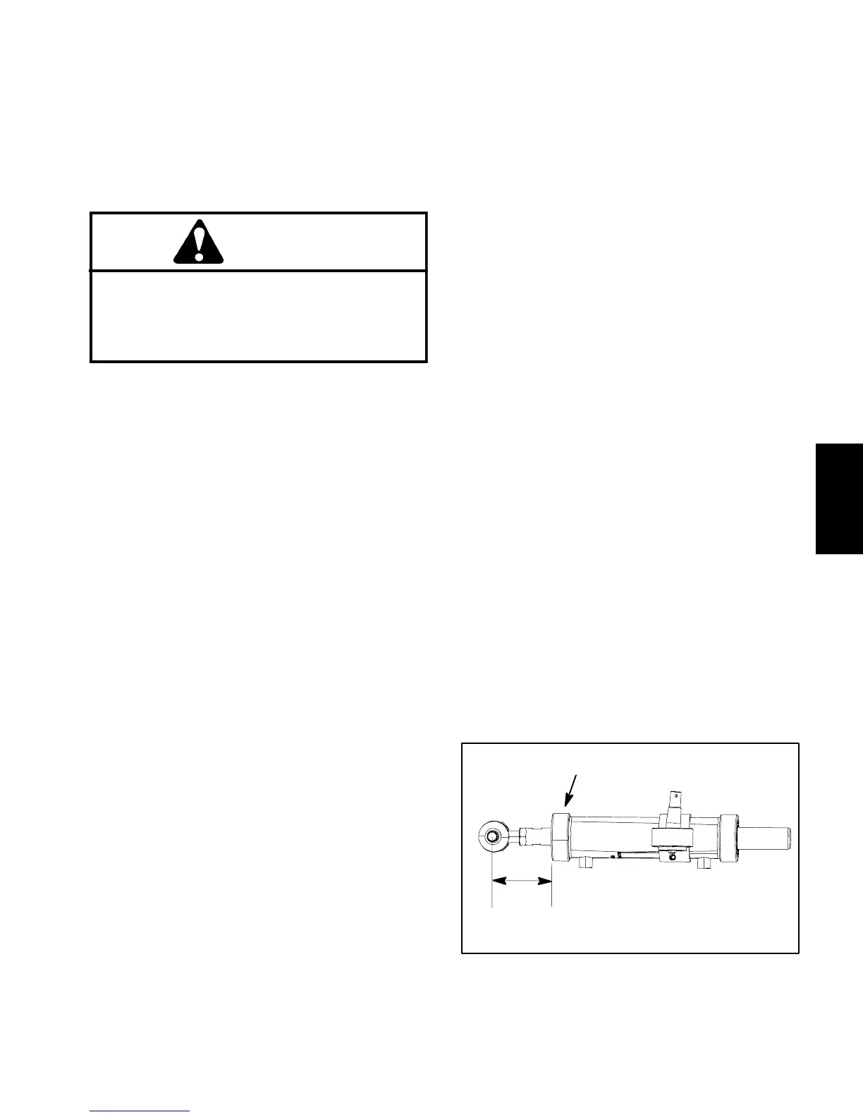
8. If necessary, remove ball joints from steering cylin-
der barrel and shaft. If ball joint is to be removed from
cylinder shaft, fully retract cylinder shaft and measure
distancefromcylinderfrontheadtocenterofballjointto
easeinstallationofballjointintocylindershaft(Fig.102).
9. If hydraulic fittings are to be removed from steering
cylinder, mark fittingorientation to allowcorrect assem-
bly. Remove fittings from steering cylinder and discard
O--rings.
Installation (Fig. 101)
1. Ifhydraulicfittingswereremovedfromsteeringcylin-
der,lubricatenewO--r ings withcleanhydraulicoil,posi-
tion O--rings to fittings and install fittings into steering
cylinder ports (see Hydraulic Fitting Installation in the
GeneralInformation section ofthis chapter).Make sure
that fittings are orientated correctly.
2. Ifremoved,pressballjointintobarrelandsecurewith
retaining ring.
3. If ball joint wasremoved from cylinder shaft, fullyre-
tractcylindershaft andthreadballjoint intoshaftso that
distancefromcylinder frontheadtocenter ofballjointis
as measured during removal process. Tighten jam nut.
4. Thoroughly clean tapers on ball joints and axle as-
sembly.
5. Position steering cylinder to machine.
6. Secure steering cylinder to axle with jam nuts (item
16).Tightenfirstjamnutandthen,whileholdingfirstjam
nut with wrench, tighten second jam nut.
7. Secure steering cylinder to RH drag link with slotted
hex nut (item 29). Install cotter pin (item 20).
8. Remove caps and plugs from hydraulic hoses and
fittings.
9. Lubricate and install new O--rings on steering cylin-
der fittings. Correctly connect hydraulic hoses to steer-
ing cylinder (see Hydraulic Hose and Tube Installation
in the General Information section of this chapter).
10.Checkoillevel inhydraulicreservoirandaddcorrect
oil if necessary.
11.Lubricate s teering cylinder ball joint grease fittings.
12.Follow Hydraulic System Start--up procedures (see
Hydraulic System Start--up in this section).
13.Check that steering cylinder does not contact the
axle or frame as cylinder moves from fully retracted to
fully extended. Also, check that distance between the
drag linksand steering stops are equalon both sides of
themachine.Ifnecessary,adjustlocationofballjointon
cylinder shaft.
Figure 102
MEASURE DISTANCE
FOR ASSEMBLY PURPOSES
FRONT HEAD
Hydraulic
System

 Loading...


