Groundsmaster 4300--D Page 6 -- 9 Chassis
6. Remove return spring and clevis pin that secure
brakecabletobrakeactuatorlever.Positionbrakecable
end away from lever.
7. Remove brake drum.
IMPORTANT: DONOThitwheel hub,pullerorwheel
motor with a hammer during wheel hub removal or
installation. Hammering may cause damage to the
wheel motor.
8. Makesurethatlocknut onwheel motorshaftisloos-
ened at least two (2) turns. Use hub puller (see Special
Tools) to loosen wheel hub from wheel motor.
9. Remove lock nut and wheel hub from motor shaft.
Discard lock nut. Locate and retrieve square key.
NOTE: Ifdesired,thecomplete brakeassemblycanbe
removed from the machine for disassembly (see step
12).
10.Remove upper and lower shoe springs from brake
shoes.
11.Remove s hoe hold down cups and hold down
springs. Removebrake shoes andhold down pinsfrom
backing plate.
12.If necessary, remove brake backing plate from ma-
chine by loosening and removing four (4) cap screws
(item 26) and lock nuts (item 27).
Installation (Fig. 6)
1. Remove rust and debris from all brake parts with a
wire brush prior to installation. Clean all parts. Inspect
brake shoe contact surfaces of the brake drum for ex-
cessive wear. Replace any worn or damaged parts.
2. If brake backing plate was removed from machine,
secure backing plate to brake bracket with four (4) cap
screws (item 26) and lock nuts (item 27).
3. Lightlylubricatebrakeshoepivotpointswithgeneral
purpose grease.
4. Position one brake shoe to the backing plate. Install
brake hold down pin and secure with hold down spring
and cup. Repeat for second brake shoe.
5. Installupper andlowershoe springstobrakeshoes.
Make sure that brake s hoes are properly positioned to
pivot and actuator points.
IMPORTANT: Before wheel hub is installed, thor-
oughly clean tapers of wheel hub and wheel motor
shaft. Make sure that tapers are free of grease, oil
and dirt.Do not useantiseize lubricant when instal-
ling wheel hub.
6. Mount square key in the w heel motor shaft, then
install the wheel hub onto the wheel motor shaft.
IMPORTANT: Do not reuse lock nut that secures
wheelhubtowheelmotorafterithasbeenremoved.
7. Install new lock nut (item 17) onto the wheel motor
shaft to secure wheel hub to motor shaft.
8. Install brake drum.
9. Positionbrakecableendtobrakeactuatorlever.Se-
cure cable to actuator lever with clevis pin and return
spring.
10.Install front wheel assembly (see Wheel Installation
in this section).
11.Check and adjust brakes.
12.Lower machine to ground.
13.Torque lug nuts evenly in a crossingpatternfrom 70
to 90 ft--lb (95 to 122 N--m). Torque lock nut (item 17)
that secures wheel hub from 315 to 385 ft--lb (427 to
521 N--m).
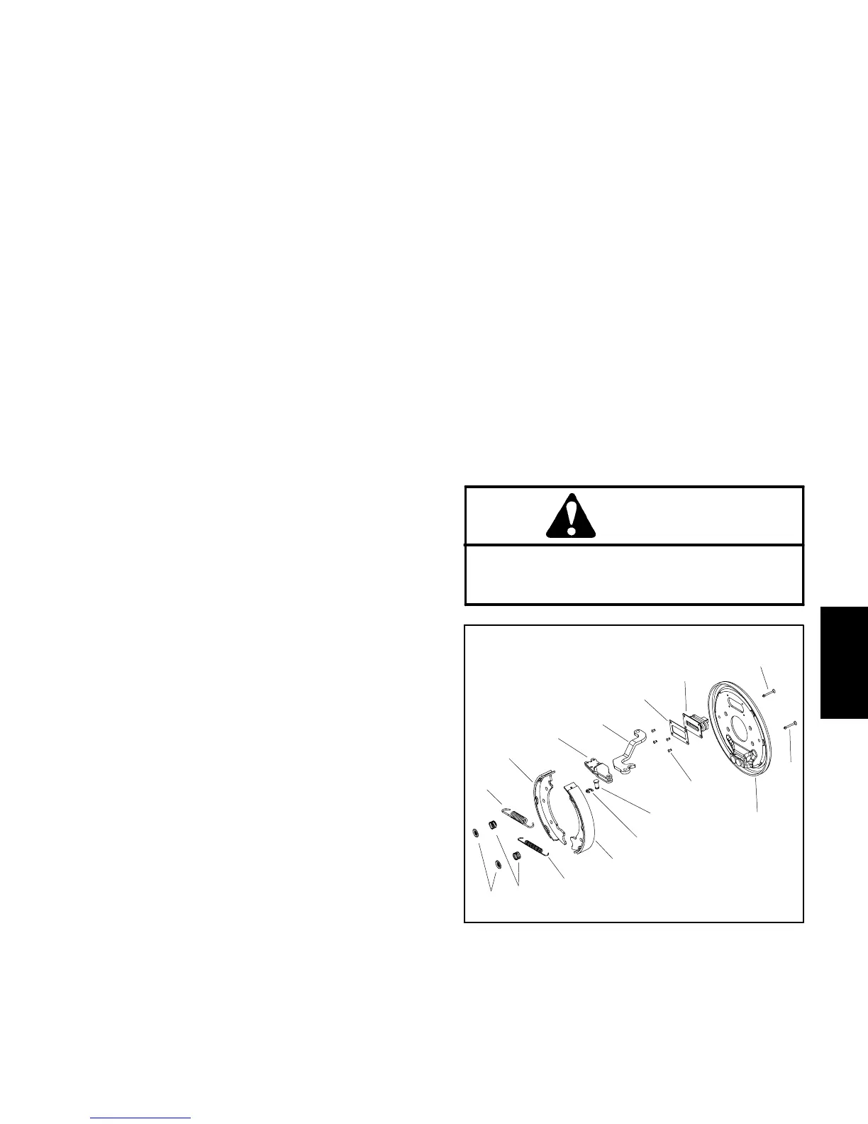
CAUTION
After servicing the brakes, always check the
brakes in a wide open, level area that is free of
other persons and obstructions.
1. Backing plate
2. Rivet (4 used)
3. Clevis pin
4. Retaining ring
5. Brake shoe
6. Lower shoe spring
7. Hold down spring
8. Hold down cup
9. Upper shoe spring
10. Brake actuator
11. Actuator lever
12. Back--up plate
13. Boot
14. Hold down pin
Figure 7
10
2
3
1
4
5
6
8
9
7
5
11
12
13
14
14
Chassis

 Loading...


