Groundsmaster 4300--D Page 6 -- 21 Chassis
IMPORTANT: When removing the seat suspension,
make sure to support the control arm to prevent
damage to the throttle cable, control arm electrical
components and control arm wiring harness.
Removal (Figs. 18 and 19)
1. Park machine on a level s urface, lower cutting
decks, stop engine, engage parking brake and remove
key from the ignition switch.
2. Disconnect negative batterycablefrom battery (see
Battery Service in the Service and Repairs section of
Chapter 5 -- Electrical System).
3. Remove seat from machine(see Operator SeatRe-
moval in this section).
IMPORTANT: Take care to not damage the throttle
cableorelectricalharnesswhenremovingseatsus-
pension from machine.
4. Tilt and support seat frame to allow access to seat
suspension fasteners.
5. Support seat suspension to prevent it from falling.
Remove four (4) flange head screws (Figure 19 item 8)
and flangenuts (Figure 19item 5)that secureseat sus-
pension to seat frame.
6. Removeseatsuspensionfrommachine.Locateand
retrieve four (4) spacers (Figure 19 item 7) from be-
tween seat suspension and seat frame.
7. Remove seat suspension components as needed
using Figures 18 and 19 as guides.
Installation (Figs. 18 and 19)
1. Installall removedseatsuspension componentsus-
ing Figures 18 and 19 as guides.
IMPORTANT: Take care to not damage the throttle
cableorelectricalharnesswheninstallingseatsus-
pension to machine.
2. Positionseatbasecoverandfour(4)spacers(Figure
19 item 7) to seat frame.
3. Position seat suspension to seat frame and secure
with four (4) flange head screws (Figure 19 item 8) and
flangenuts( Figure19item5).Useforwardholesinseat
brackets to mount suspension.
4. Install seat to machine (see Operator Seat Installa-
tioninthissection). Makesure toconnectharnesselec-
trical connector to the seat switch.
5. Connect negative battery cable to battery (see Bat-
teryServiceintheServiceandRepairssectionofC hap-
ter 5 -- Electrical System).
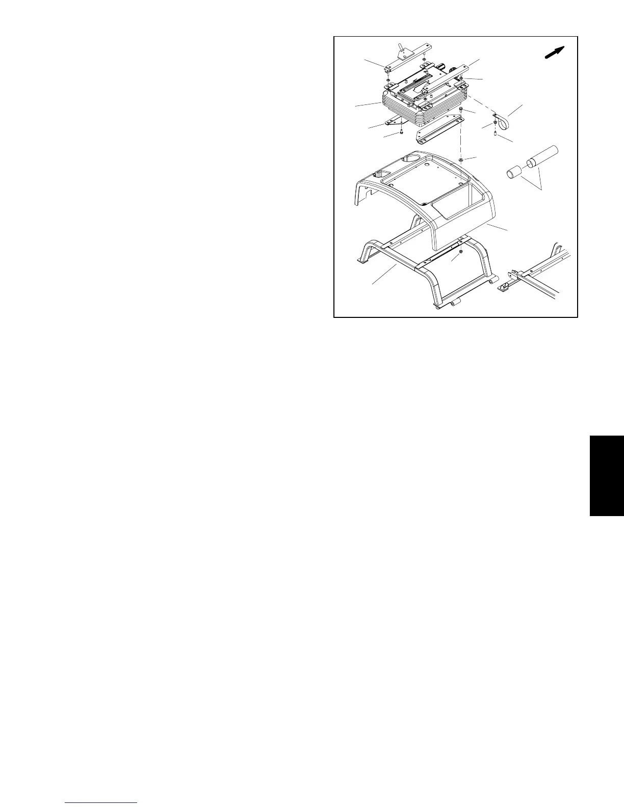
1. Seat suspension
2. Seat bracket (2 used)
3. Screw (4 used)
4. Seat frame
5. Flange nut (8 used)
6. Seatbase cover
7. Spacer (4 used)
8. Flange screw (4 used)
9. Cap (4 used)
10. Manual tube
11. R--clamp (2 used)
12. Flat washer (4 used)
13. Seat adjuster
14. Seat adjuster w/latch
Figure 19
1
2
4
3
5
6
7
8
FRONT
5
9
10
11
12
13
14
Chassis

 Loading...


