Groundsmaster 4300--D Page 6 -- 25 Chassis
C. Remove screw that secures r--clamp to lift arm.
Position r--clamp and hydraulic hoses away from lift
arm.
D. Pivot lift cylinder rod end away from lift arm.
4. Remove fasteners that secure bridge plate (item 1)
and bulkhead bracket (item 16) to machine. Position
bulkhead bracket with attached hydraulic hoses away
from lift arm. Remove bridge plate.
5. Slide rear lift arm from lift arm pivot shaft.
6. Inspect flange bushings in lift arm for wear or dam-
age. If necessary, replace bushings:
A. Use bushing removal tool to extract both flange
bushings from the lift arm. Take care to not damage
the lift arm bore.
B. Clean the insideof the boreto remove anydirtor
foreign material.
C. Applygreasetotheinsideandoutside ofthenew
flange bushings.
D. Use an arborpress to install the bushingsinto lift
arm. Bushings should be pressed until bushing
flange is against lift arm bore.
E. After bushing installation, make sure that lift arm
slides easily onto pivot shaft. If binding is noted, lo-
cate and correct source of binding.
7. If necessary, remove cap screw that secures pivot
shaft (item 11) in lift arm. Remove pivot shaft from lift
arm.
8. Ifnecessary,removerollpin(item13)andliftarmpiv-
ot shaft (item 9) from frame. Discard roll pin.
Installation (Fig. 22)
1. If lift arm pivot shaft (item 9) was removed from
frame, apply antiseize lubricant to pivot shaft surface
andinsertshaftintoframe.Alignholesinframeandpivot
shaft. Secure pivot shaft with new roll pin (item 13).
2. If pivot shaft (item 11) was removed from lift arm, in-
sert pivot shaft into lift arm and secure with cap screw
(item 14).
3. Slide rear lift arm onto pivot shaft.
4. Secure rear lift arm to machine:
A. ApplyPermatexBlueGelThreadlocker(orequiv-
alent) to threads of screws (items 4, 6 and 8).
B. Position bridge plate and bulkhead bracket with
attachedhydraulichosestoliftarmandframebrack-
et.
C. Install screws, flat washers (items 5 and 10) and
flangenut (item7)to bridgeplate,bulkheadbracket,
pivot shafts and frame bracket.
D. Torque 1/2” fasteners (items 4 and 8) from 75 to
95ft--lb(102to 128 N--m).Then,torque5/8”fasten-
ers(item 6)from135 to165 ft--lb (183to223 N--m).
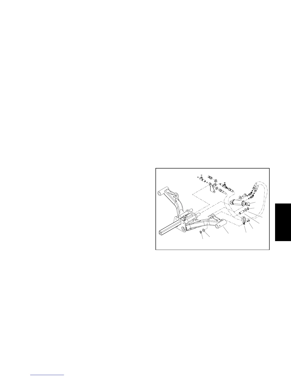
5. Connect lift cylinder to lift arm (Fig. 21):
A. Align lift cylinder rod end to lift arm mounting
holes.
B. Slide cylinder pin with retaining ring and thrust
washer through the lift cylinder and lift arm.
C. Install second thrust washer on pin and secure
with second retaining r ing.
D. Position r--clamp and hydraulic hoses to lift arm.
Secure r--clamp with screw.
6. Mountcutting decktoliftarm (seeCutting DeckCar-
rier Frame Installation in the Service and Repairs sec-
tion of Chapter 7 -- Cutting Decks).
7. Lubricate lift arm and lift cylinder grease fittings.
1. Lift arm (#2 shown)
2. Lift cylinder
3. Retaining ring
4. Thrust washer
5. Cylinder pin
6. R--clamp
7. Screw
Figure 23
7
3
1
2
5
6
4
3
4
Chassis

 Loading...


