Groundsmaster 4300--D Cutting DecksPage 7 -- 15
3. From the roller tube end with only the inner seal
installed, carefully install the roller shaft into the roller
tube. Make sure that seals are not damaged as shaft is
installed.
4. Install new bearing and outer seals into second end
of roller tube:
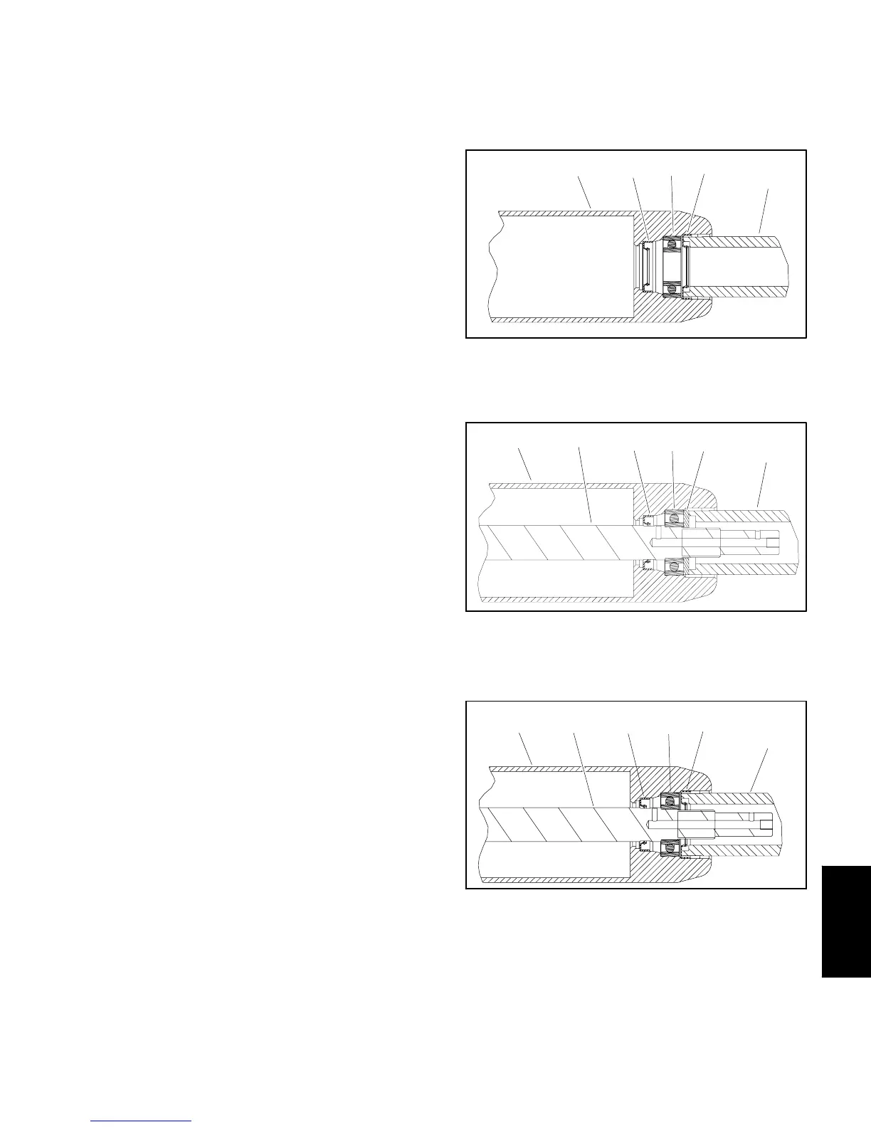
A. Position asecondnew bearingtoroller shaftand
tube. Position washer (see Special Tools in this
chapter) on bearing to allow pressing on both inner
and outer bearing r aces simultaneously.
B. Use washer and bearing/outer seal tool (see
SpecialToolsinthischapter)withasoftfacehammer
to fully seat bearing (Fig. 15). After bearing installa-
tion, make sure that shaft freely rotates and that no
binding is detected. If necessary, lightly tap bearing
and/or shaft ends to align shaft and bearings. Re-
move washer from roller.
C. Apply a small amount of grease around the lip of
both outer seals.
D. Carefully install first outer seal into roller tube
making sure that seal lip (and garter spring) faces
endoftube.Usebearing/outersealtool(seeSpecial
Toolsin this chapter)and soft facehammer to lightly
seat seal (Fig. 16). Make sure that shaft and bear-
ings still freely rotate after seal installation.
E. Using the same process, install second outer
sealmakingsuretonotcrushtheinstalledouterseal.
Again, make sure that shaft and bearings still freely
rotate.
IMPORTANT: Make sure that all grease is removed
from shaft threadsto prevent bearinglock nut loos-
ening.
5. Thoroughly clean threads on both ends of roller
shaft.
NOTE: If original bearing lock nut(s) are being used,
apply Loctite #242 (or equivalent) to threads of lock
nut(s).
6. Install bearing lock nut onto each end of the roller
shaft. Make sure that outerseals are not damaged dur-
ing nutinstallation. Torque lock nutsfrom 50 to 60 ft--lb
(68to81N--m).
7. If set screw was removed from either end of roller
shaft,applyLoctite#242(orequivalent)tothreadsofre-
movedset screwand installinto rollershaft. Tightenset
screw until it bottoms in shaft and is recessed in shaft.
IMPORTANT: When roller assembly is installed to
cutting deck, make sure that grease groove in each
rollermount aligns withthe grease holein each end
of roller shaft.
NOTE: After roller is installed to cutting deck, lubricate
roller grease fittings, rotate roller to properly distribute
grease inbearings and clean excess grease fromroller
ends. A properly assembled roller should rotate with
less than 5 in--lbs (0.68 N--m) resistance.
1. Roller tube
2. Inner seal
3. Bearing
4. Outer seal
5. Bearing/outer seal tool
Figure 14
3
4
2
1
5
1. Roller tube
2. Roller shaft
3. Inner seal
4. Bearing
5. Washer
6. Bearing/outer seal tool
Figure 15
34
2
1
5
6
1. Roller tube
2. Roller shaft
3. Inner seal
4. Bearing
5. Outer seal
6. Bearing/outer seal tool
Figure 16
3
4
2
1
5
6
Cutting Decks

 Loading...


