Groundsmaster 4300--D Hydraulic SystemPage 4 -- 39
CAUTION
Beforeopeninghydraulicsystem,operateallhy-
draulic controls to relieve system pressure and
avoid injury from pressurized hydraulic oil. See
RelievingHydraulicSystemPressurein theGen-
eral Information section of this chapter.
4. Raise and support operator seat to allow access to
hydraulic pump.
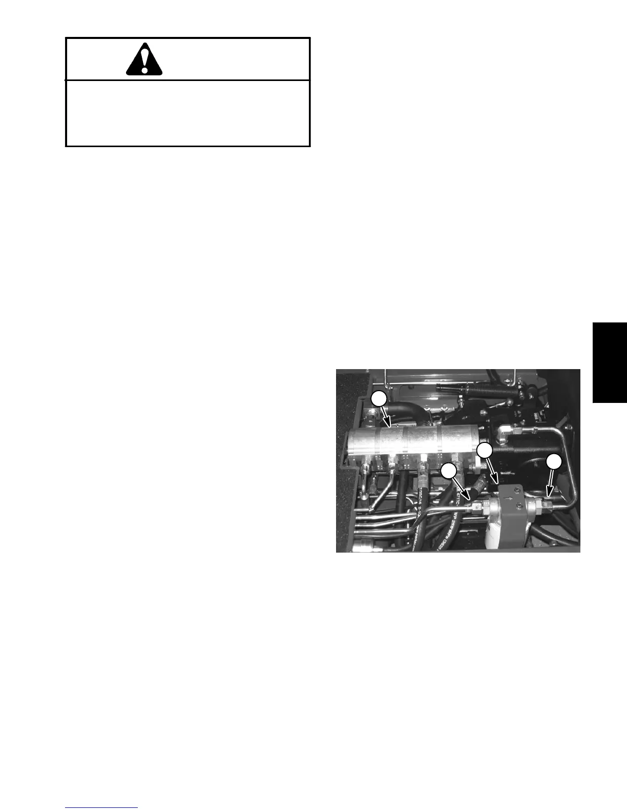
5. Thoroughly clean the ends of the hydraulic tubes
connected to the oil filter and traction pump inlets (Fig.
40). Disconnect hydraulic tubes from oil filter inlet and
tractionpumpinlet.Removetwo(2)flangeheadscrews
that secure oil filter adapter to frame. Remove oil filter
assembly and hydraulic tube from machine.
IMPORTANT: Make sure that the oil flow indicator
arrow on the flow meter is showing that the oil will
flow from thehydraulic tube, throughthe tester and
into the traction pump.
6. Install testerwith pressuregauges andflow meterin
place of the removed oil filter assembly and hydraulic
tube. Connect tester inlet hose to the hydraulic tube.
Connect the tester outlet hose to the traction pump fit-
ting.Makesuretheflowcontrolvalveontesterisful-
ly open.
7. Make sure that the traction pedal is in neutral, the
steeringwheelisstationaryandtheparkingbrakeisen-
gaged.
8. Startengineandrunatidlespeed.Checkforanyhy-
draulic leakage from test connections and correct be-
fore proceeding with test.
9. Move throttle to full speed (3200 RPM).Usea
tachometer to verify that engine speed is correct.
IMPORTANT: The gear pump is a positive displace-
ment type. If pump flow is completely restricted or
stopped, damage to the pump, tester or other com-
ponents could occur.
10.While watching pressure gauges, slowly close the
tester flow control valve until 800 PSI (55 bar) is ob-
tained on gauge.
FLOW TESTER READING TO BE: A pump in good
condition should have a flow of approximately 4.9
GPM (18.5 LPM) at 800 PSI (55 bar).
11.Open the tester flow control valve, stop engine and
record test results.
12.Ifflowislessthan4.4 GPM (16.6 LPM) orapressure
of 800 PSI (55 bar) cannot beobtained, consider that a
pump problem exists. Check for restriction in pump in-
take line. If intake is not restricted, remove gear pump
and repair or replace pump as necessary (see Gear
Pump in the Service and Repairs section of this chap-
ter).
NOTE: Iftheflowfromgearpump(P3)islow,theopera-
tionofboththechargecircuitand thesteering circuitwill
be affected.
13.After testing is completed, make sure that engine is
stopped, then relieve hydraulic system pressure (see
RelievingHydraulic SystemPressure intheGeneralIn-
formation section of this chapter). Remove tester and
then install oil filter assembly and hydraulic tube to ma-
chine.
14.Lower and secure operator seat.
1. Hydraulic tube
2. Oil filter / filter adapter
3. Hydraulic tube
4. Gear Pump (P3)
Figure 40
3
2
4
1
Hydraulic
System

 Loading...


