Groundsmaster 4300--D Hydraulic SystemPage 4 -- 45
3. Read Precautions For Hydraulic Testing in this sec-
tion.
CAUTION
Beforeopeninghydraulicsystem,operateallhy-
draulic controls to relieve system pressure and
avoid injury from pressurized hydraulic oil. See
RelievingHydraulicSystemPressurein theGen-
eral Information section of this chapter.
4. Raise and support operator seat to allow access to
hydraulic deck control manifold.
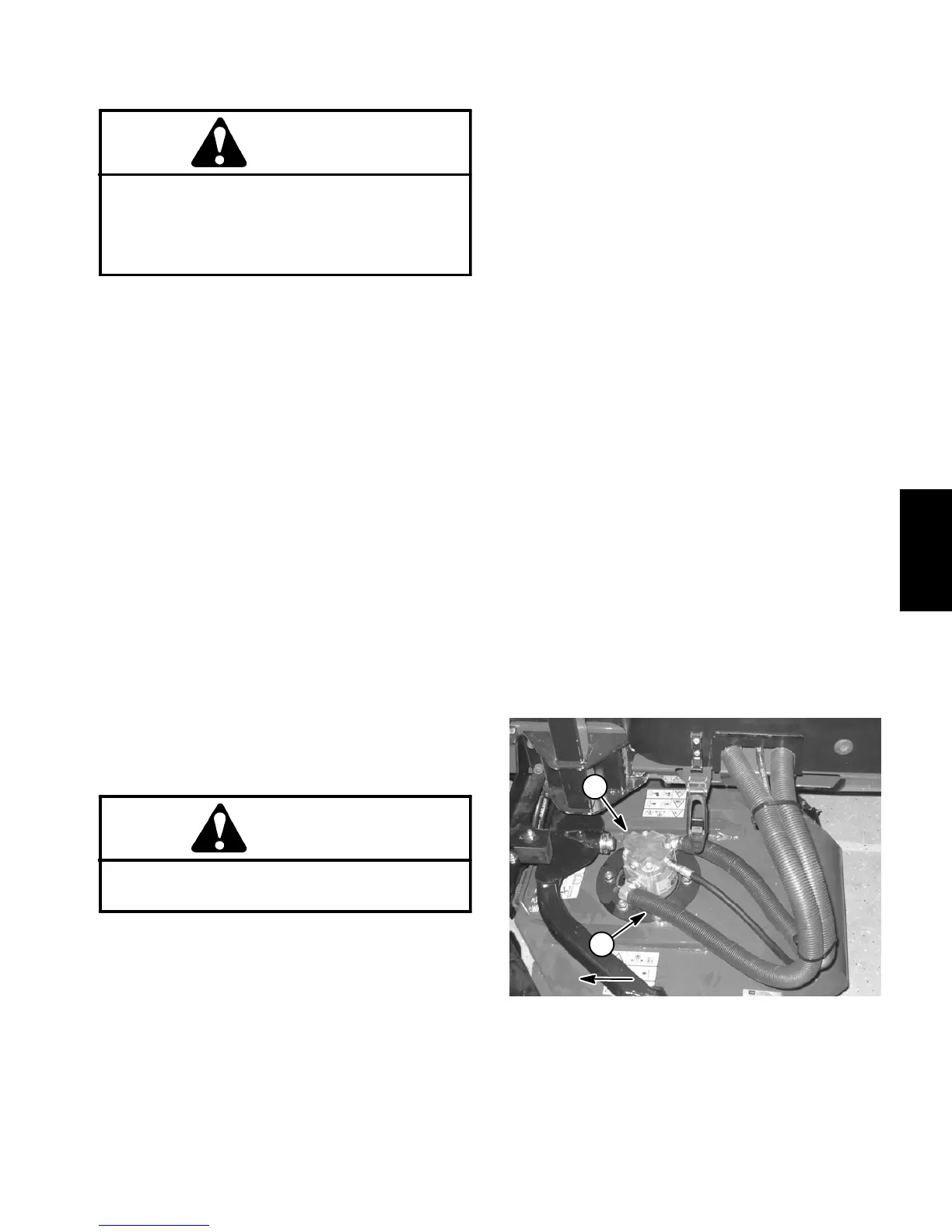
5. Thoroughlycleanjunctionofhydraulicinlethoseand
deck motor fitting on left side cutting deck for the relief
valvetobetested. Disconnecthose fromdeck motorfit-
ting (Fig. 46):
#2 cutting deck (left rear) for relief valve (PRV1)
#4 cutting deck (left front) for relief valve (PRV2)
IMPORTANT: Make sure that the oil flow indicator
arrow on the flow meter is showing that the oil will
flowfromthedisconnectedhose,throughthetester
and into the deck motor.
6. Install tester with pressure gauge and flow meter in
series with the disconnected hose and hydraulic fitting
on deck motor. Make sure the flow control valve on
tester is fully open.
7. After installing tester, start engine and run at idle
speed. Check for any hydraulic leakage from test con-
nections and correct before proceeding with test.
8. Move throttle to full speed (3200 RPM) .
CAUTION
Keepawayfrom cutting decks during testtopre-
vent personal injury from rotating blades.
9. Have a second person occupy seat, press PTO
switchtoONandthenmovejoystickleverforwardtoen-
gage cutting decks.
IMPORTANT: When performing this test, do not
hold over reliefany longer thannecessary toobtain
pressure reading.
10.Watchpressure gaugecarefullywhileslowlyclosing
the tester flow control valve. As the relief valve lifts, the
pressure gauge needle w ill momentarily stop.
NOTE: Oncethe reliefvalvehasopened, systempres-
sure may continue to increase.
11.As the relief valve lifts, system pressure should be:
Approximately 2500 PSI (175 bar) for relief valve
(PRV1)
Approximately 3500 PSI (241 bar) for relief valve
(PRV2)
12.Openthetesterflowcontrolvalve,disengagecutting
decks and stop the engine.
13.If pressure is incorrect, remove PRV valve on mow
manifold and clean or replace valve (see Deck Control
Manifold Service in the Service and Repairs section of
this chapter).Also,if pressureis stilllow afterv alve ser-
vice, check for restriction in pump intake line. Gear
pump (P2) (front cutting deck circuit) and/or pump (P1)
(rear cutting deck circuit) could also be suspected of
wear, damage orinefficiency (see GearPump (P1) and
(P2) Flow Test in this section).
14.After testing is completed, make sure that engine is
stopped, then relieve hydraulic system pressure (see
RelievingHydraulic SystemPressure intheGeneralIn-
formation section of this chapter). Remove tester from
machine and connect hydraulic hose to deck motor fit-
ting.
15.Lower and secure operator seat.
1. Cutting deck motor (#2 shown)
2. Deck motor inlet hose
Figure 46
1
2
FRONT OF MACHINE
Hydraulic
System

 Loading...


