Groundsmaster 4300--D Hydraulic SystemPage 4 -- 51
5. Thoroughly cleantest port(G4)on bottomoflift con-
trol manifold. C onnect a 5000 PSI (350 bar) pressure
gauge to test port.
6. After installing pressure gauge to manifold test port,
startengineandrunatidlespeed.Checkforanyhydrau-
licleakagefromtestconnectionsandcorrectbeforepro-
ceeding with test.
7. Move throttle to full speed (3200 RPM) .
IMPORTANT: Do not allow pressure to exceed 2500
PSI (172 bar).
IMPORTANT: While performing this test, hold joys-
tick lever in the raise position only long enough to
get a system pressure reading. Holding the lever in
raise for an extended period may damage system
components.
8. MakesurethatPTOswitchisOFFandthenpulljoys-
tickleverrearwardtopressurizeliftcircuit.Whileholding
lever in the raise (rearward) position, watch pressure
gauge carefully. As the cutting decks fully raise and the
lift relief valve lifts, system pressure should be:
Approximately 2000 PSI (138 bar)
9. Return the joystick lever to the neutral position and
stop the engine.
10.If measured pressure is incorrect, remove pressure
reducingvalve(PRV)fromliftcontrolmanifoldandclean
orreplacevalve(seeLiftControlManifoldServiceinthe
Service and Repairs section of this chapter). Also, if lift
circuitpressureislow,checkforrestrictioningearpump
intake line. Internal lift cylinder leakage would also
cause low lift circuit pressure (see Lift Cylinder Internal
LeakageTestinthissection).Gearpump(P4)couldalso
besuspectedofwear,damageorinefficiency(seeGear
Pump (P4) Flow Test in this section).
11.After testing is completed, make sure that engine is
stopped, then relieve hydraulic system pressure (see
RelievingHydraulic SystemPressure intheGeneralIn-
formation section of this chapter). Disconnect pressure
gauge from lift control manifold test port.
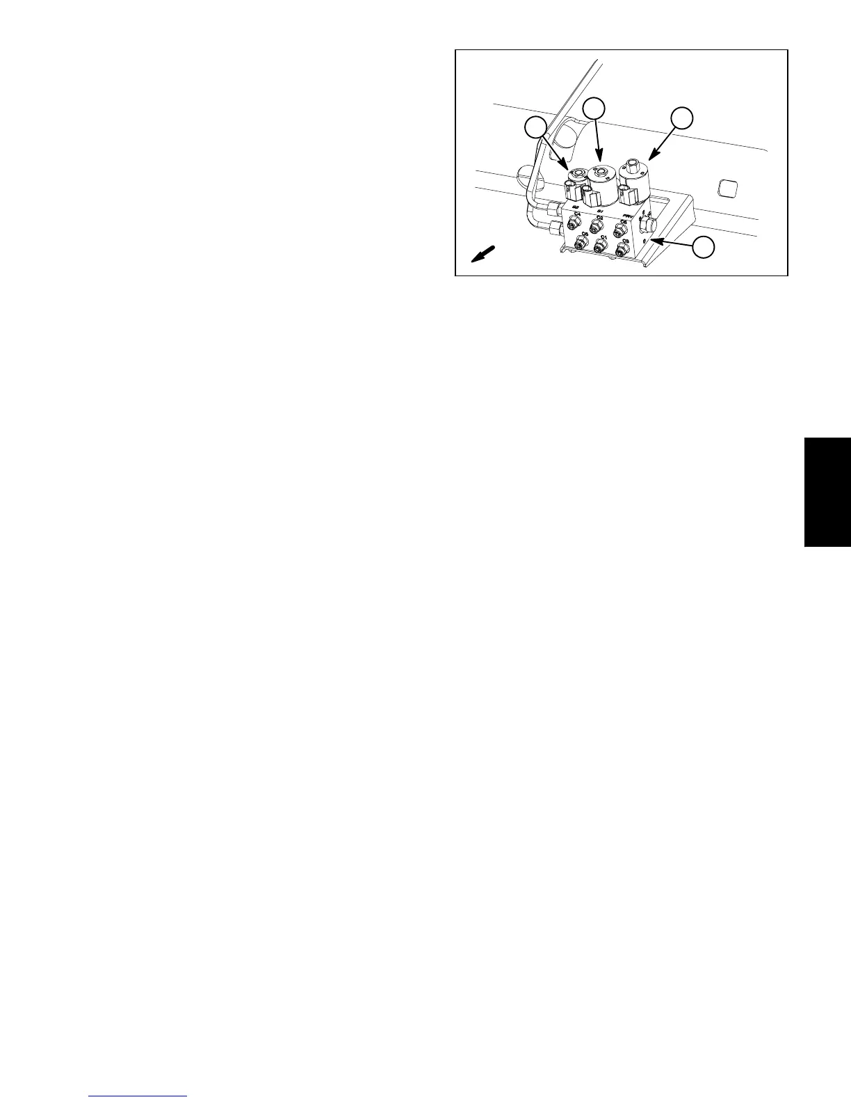
1. Lift control manifold
2. SV1 solenoid
3. SV2 solenoid
4. PRV solenoid
Figure 52
4
1
3
2
FRONT
Hydraulic
System

 Loading...


