Groundsmaster 4300--D Hydraulic SystemPage 4 -- 55
IMPORTANT: When capping lift cylinder fitting and
hydraulic hose end, use a steel cap and plug to en-
sure that fluid leakage will not occur. Plastic plugs
will not hold hydraulic pressure that will be devel -
oped during this t est procedure.
4. Place a steel cap on the open lift cylinder fitting to
sealthe liftcylinder. Also,install a steelplug inthe open
endofthedisconnectedhosetopreventleakageorcon-
tamination.
5. Slowly lower the jack and remove it from under the
lift arm. The cutting deck should settle slightly and then
be supported by the capped lift cylinder.
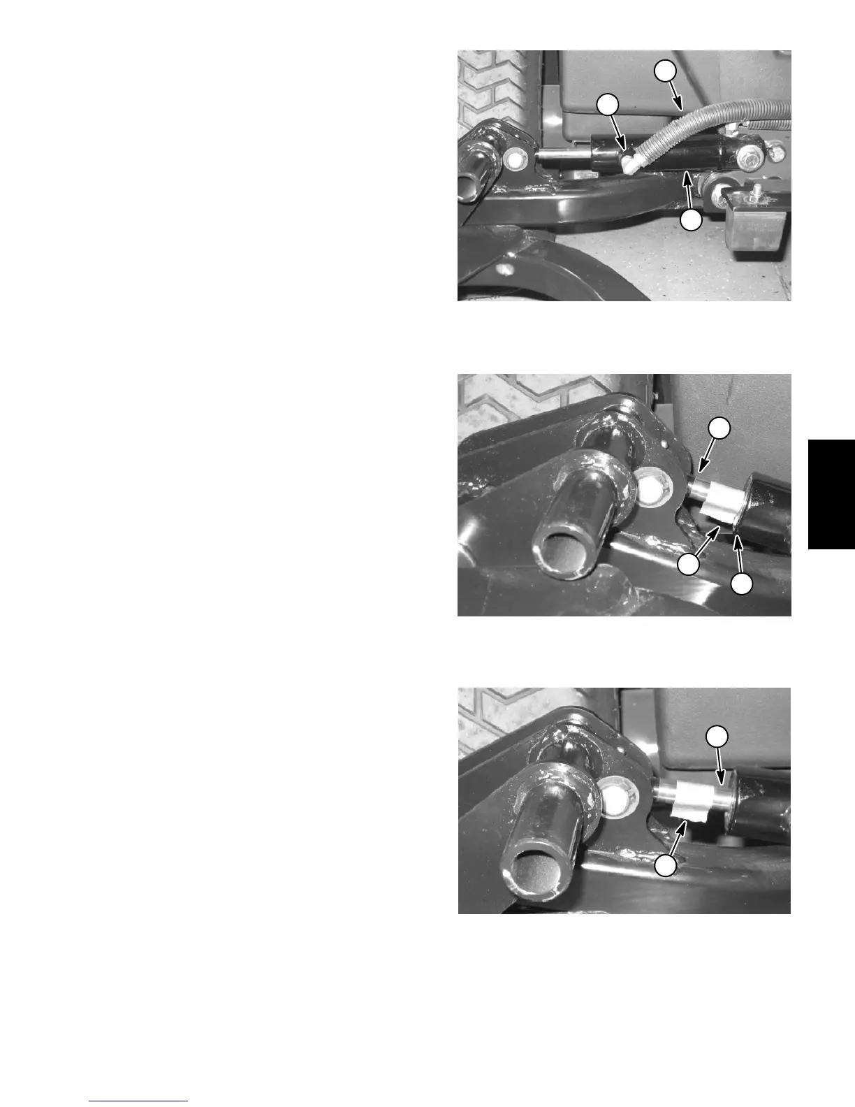
6. Markthepositionoftheliftcylinderrodattheliftcylin-
der head with a piece of tape (Fig. 57).
7. Leave the machine parked for two (2) hours and
monitor the lift cylinder. The weight of the cutting deck
may cause the lift cylinder to gradually extend. Use the
tape location to determine lift cylinder rod movement
(Fig. 58).
A. If lift cylinder rod movement is less than 1.250”
(31.7mm)aftertwo(2)hours,makesurethatthecut-
ting deck has not settled to the ground. If the cutting
deckiss tillsuspendedaftertwo(2)hoursandliftcyl-
inder rod movement is less than 1.250” (31.7 mm),
consider that the lift cylinder is in good condition. A
cylinder in good, usable condition will show minimal
movement.
B. Rod movementin excessof1.250”(31.7mm) af-
ter two (2) hours indicates that the lift cylinder may
have internal seal damage or excessive wear. Re-
move and inspect the lift cylinder (see Lift Cylinder
and Lift Cylinder Service in the Service and Repairs
section of this chapter).
8. Once lift cylinder condition has been determined,
use a jack to raise the lift arm slightly which will remove
the load from the lift cylinder. Leave the jack to support
the lift arm and to prevent it from lowering. Remove the
cap from the cylinder fitting and the plug from the hy-
draulichose.Connectthehydraulichosetotheliftcylin-
der fitting.
9. Carefully remove jack from under the lift arm. Start
engineandoperateliftcylinders throughseveralupand
down cycles. Stop the engine and check for any leak-
age.
10.If needed,repeatsteps 2through10 forother liftcyl-
inders.
11.After testing is complete, check oil level in hydraulic
reservoir and adjust if necessary.
1. Lift cylinder (#5 shown)
2. Cylinder rod end fitting
3. Hydraulic hose
Figure 56
3
2
1
1. Lift cylinder rod
2. Lift cylinder head
3. Tape (initial position)
Figure 57
2
1
3
1. Tape (after 2 hours) 2. Cylinder rod movement
Figure 58
2
1
Hydraulic
System

 Loading...


