Groundsmaster 4300--D Hydraulic SystemPage 4 -- 67
Removal (Fig. 65)
1. Parkthemachineonalevelsurface,engageparking
brake, lower cutting decks and stop engine. Remove
key from the ignition switch.
2. Remove two(2) flangeheadscrews andflange nuts
that secure drive shaft guard hoop (item 4) to machine
frame. Remove guard.
3. Remove two(2) capscrews (item5) andflange nuts
(item9)thatsecuredriveshaftyoketopistonpumpinput
shaft.
4. Removesix(6)capscrews(item7)thatsecuredrive
shaft flange to engine flywheel.
5. Remove drive shaft assembly from machine.
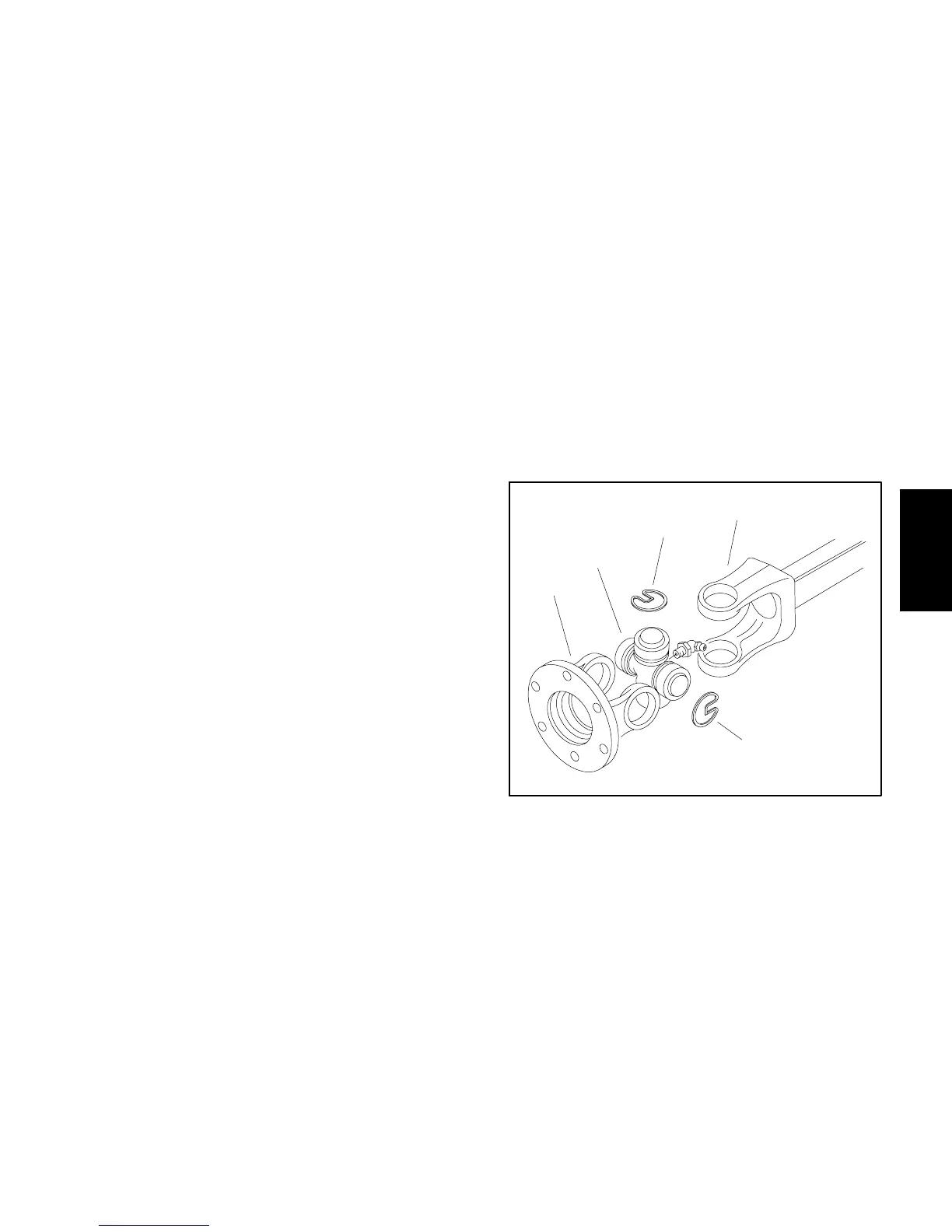
Drive Shaft Cross and Bearing Service (Fig. 66)
1. Remove snap rings that secure bearings in yokes.
IMPORTANT: Yokes must be supported when re-
moving and installing bearings to prevent damage.
2. Use a press to remove cross and bearings from
yokes. Thoroughly clean drive shaft yokes.
3. To install new cross and bearings:
A. Apply acoatingofgrease tobearingboresin end
yoke and shaft yoke.
B. Press one bearing partially into yoke.
C. Insert cross into yoke and bearing.
D. Holdcrossinalignmentandpressbearinginuntil
it hits the yoke.
E. Install snap ring into yoke groove to secure
installed bearing.
F. Place second bearing into yoke bore and onto
crossshaft.Press bearingintoyoke andsecurewith
snap ring.
G. Repeat procedure for other yoke.
H. Greasecrossuntilgreasecomesoutofallfour(4)
cups.
4. Make surethatassembled jointmoves withoutbind-
ing. Slight binding can usually be eliminated by lightly
rapping the yokelugs with a soft facedhammer. If bind-
ing continues, disassemble joint to identify source of
binding.
Installation (Fig. 65)
1. Applyantiseizelubricanttotractionpumpinputshaft.
2. Positiondriveshaftassemblytoengineandpumpin-
put shaft.
3. Apply Permatex Blue Gel Threadlocker (or equiva-
lent) to threads of cap screws (item 7) that secure drive
shaft flange to engine flywheel. Secure drive shaft
flange to flywheel with six (6) cap screws (item 7).
Torque cap screws from 34 to 42 ft--lb (46 to 56 N--m).
4. Slide driveshaftyokeon pumpinputshaftso yokeis
flush with end of input shaft. Secure drive shaft yoke to
pump input shaft with two (2) cap screws (item 5) and
flange nuts (item 9).
5. Position drive shaft guard hoop to machine frame
and secure with two ( 2) flange head screws and flange
nuts.
6. Lubricate grease fittings on drive shaft.
1. End yoke
2. Cross and bearing kit
3. Snap ring (4 used)
4. Shaft yoke
Figure 66
1
2
3
4
3
Hydraulic
System

 Loading...


