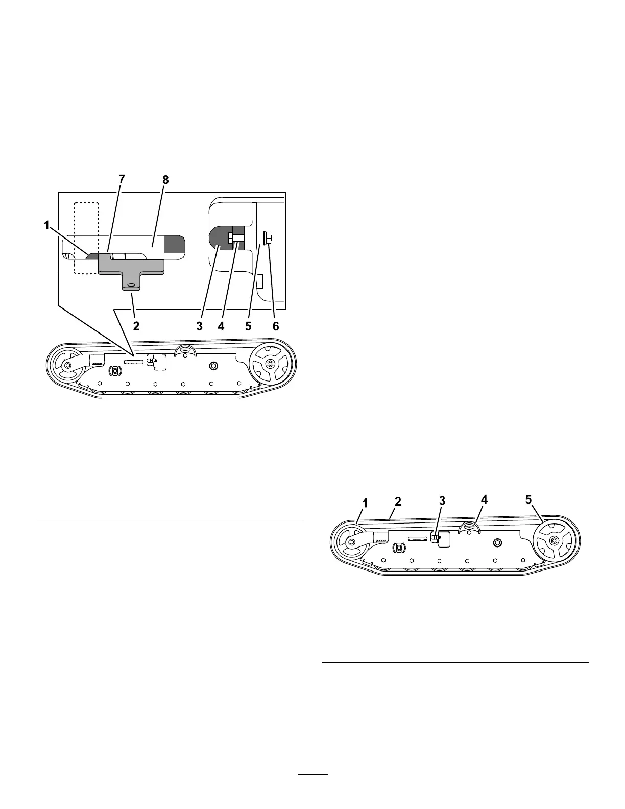
AdjustingtheTrackTension
Ifyouplacethetabofthetensioningtoolalongthe
rearedgeofthetensionnut,theotherendofthe
tensioningtoolshouldalignwiththeedgeofthe
tensionarmasshowninFigure40.Ifthedistanceis
notcorrect,adjustthetracktensionusingthefollowing
procedure:
Note:Ifthetensioningtoolisnotavailable,the
distancebetweenthenutandedgeofthetensionarm
shouldbe7.1cm(2-13/16inches).
g202806
Figure40
LeftTrackShown
1.Tensionnut
5.Spacer
2.Tensioningtool(equalto
7.1cmor2-13/16inches)
6.Nut
3.Tensioningbolt7.Tab
4.Bolt(1/4x1-5/8inches)
8.Tensionarm
1.Parkthemachineonalevelsurface,move
themotion-controlleverstotheNEUTRAL-LOCK
position,engagetheparkingbrake,andlower
thehopper.
2.Shutofftheengine,andremovethekey.Allow
theenginetocool.
3.Cleanthetrackswithhigh-pressurewater.
Important:Ensurethatyouuse
high-pressurewatertowashonlythetrack
area.Donotuseahigh-pressurewasher
tocleantherestofthemachine.Donot
usehighpressurewaterbetweenthedrive
sprocketandthemachineoryoumay
damagethemotorseals.High-pressure
washingcandamagetheelectricalsystem
andhydraulicvalvesordepletegrease.
4.Raisethemachinesothatthetracksareoffthe
ground.
5.Cleanthedrivesprocket,thefrontwheel,and
theroadwheels.Theroadwheelsshouldspin
freelywhenclean.
6.Removethebolt(1/4x1-5/8inches),spacer,
andnut(Figure40).
7.Turnthetensioningbolttoadjustthedistance
betweenthetensionnutandtheendtangent
ofthetensiontubeuntilthedistanceiscorrect,
asshowninFigure40.
8.Aligntheclosestnotchinthetensioningboltto
theboltholeandsecurethetensioningboltwith
thebolt(1/4x1-5/8inches),spacer,andnut
(Figure40).
ReplacingtheTracks
Replacethetrackswhentheyarebadlyworn.
1.Parkthemachineonalevelsurface,move
themotion-controlleverstotheNEUTRAL-LOCK
position,engagetheparkingbrake,andlower
thehopper.
2.Shutofftheengine,andremovethekey.Allow
theenginetocool.
3.Lift/supportthesideofthemachinetobeworked
onsothatthetrackis7.6to10cm(3to4
inches)offtheground.
4.Removetheretainingboltforthetensioning
screw.
5.Releasethedrivetensionbyturningthe
tensioningscrewclockwise(Figure40and
Figure41).
g186008
Figure41
1.Frontwheel4.Roadwheel
2.Track5.Drivesprocket
3.Tensioningscrewand
retainingbolt
6.Removethetrackatthetopofthefrontwheel,
peelingitoffthewheelwhilerotatingthetrack
forward.
7.Whenthetrackisoffthefrontwheel,removeit
fromthedrivesprocketandroadwheels(Figure
41).
30
 Loading...