2.Shutofftheengine,andremovethekey.Allow
theenginetocool.
3.Lowerthecushionandremovethefueltank;
refertoRemovingtheFuelT ank(page27).
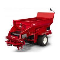
4.Removethe9bolts(5rear,4side)fromtheskid
plateandremovetheskidplate(Figure51).
g325648
Figure51
1.Rearbolts(5)3.Sidebolts(4)
2.Skidplate
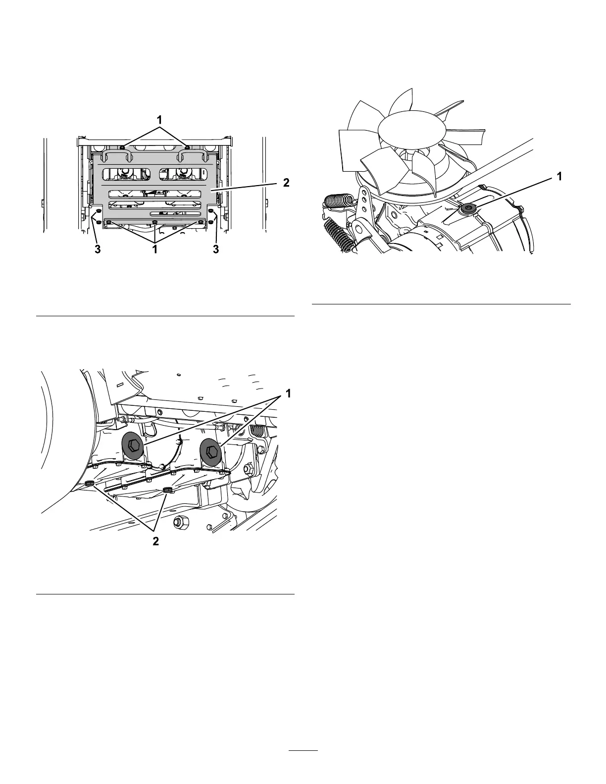
5.Locatethedrainpluginthebottomofeach
transmission,thenplaceadrainpanunderthe
plugs(Figure52).
g203515
Figure52
1.Hydrauliclters
2.Drainplugs
6.Removethedrainplugsandallowthehydraulic
uidtofullydrainfromthemachine.
7.Removethehydraulic-ltercapandhydraulic
lterfromeachtransmission(Figure52).
8.Installanewhydrauliclterwiththespringside
facingoutandthehydraulic-ltercapforeach
transmission.T orqueto13to15N∙m(115to
135in-lb).
9.Installthedrainplugs.
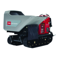
10.Loosentheventplugineachtransmissionuntil
loose(Figure53).
Note:Thisallowsairtoescapethehydraulic
systemasyouaddhydraulicuid.
g203517
Figure53
1.Ventplug
11.Slowlyaddapproximately6.2L(208oz)uid
totheexpansiontankuntilitstartstocomeout
oftheventplugs.
Important:Usetheuidspeciedin
Hydraulic-FluidSpecications(page34)or
equivalent.Otheruidscouldcausesystem
damage.
Important:Monitorthelevelofuidinthe
expansiontanksothatyoudonotoverllit.
12.Tightentheventplugs.
13.Addhydraulicuidtotheexpansiontankuntilit
reachestheuidline(Figure49).
Important:Donotoverll.
14.Installtheexpansion-tankcap.
15.Installtheskidplate(Figure51).
16.Installthefueltank;refertoRemovingtheFuel
Tank(page27).
17.Starttheengineandletitrunforabout2minutes
topurgeairfromthesystem.
18.Shutofftheengineandcheckforleaks.
35
 Loading...