EasyManua.ls Logo

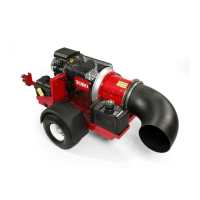
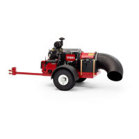
Toro Pro Force 44552TE User Manual

Toro Pro Force 44552TE
134 pages
To Next Page IconTo Next Page
Page #1 background imageLoading...
Page #1 background image
FormNo.18237SLRevA
ProForce
®
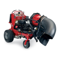
DebrisBlower
Models44552,44552TE,44553&44554
©2019—TheToro®Company
8111LyndaleAvenueSouth
Bloomington,MN55420
OriginalInstructions(EN)
Contactusatwww.Toro.com.
AllRightsReserved

Table of Contents

Question and Answer IconNeed help?

Do you have a question about the Toro Pro Force 44552TE and is the answer not in the manual?

Toro Pro Force 44552TE Specifications

General IconGeneral
BrandToro
ModelPro Force 44552TE
CategoryBlower
LanguageEnglish

Summary

Chapter 1: Safety

Safety Instructions

Explains DANGER, WARNING, CAUTION, and IMPORTANT notices.

Think Safety First

Covers hazards like starting, burns, fires, asphyxiation, and modifications.

Chapter 2: Specifications and Maintenance

Torque Specifications

Lists fastener torque values and factors affecting them.

Chapter 3: Troubleshooting

GEARS – The Systematic Approach to Defining, Diagnosing and Solving Problems

Outlines a structured method for problem diagnosis and resolution.

Starting Problems

Lists common starting issues, causes, and corrective actions.

General Operation Problems

Addresses issues with engine operation, charging, and shutdowns.

Chapter 4: Engine

Service and Repairs

Details procedures for fuel tank, evaporative control, and engine removal.

Chapter 5: Electrical System

Electrical System Quick Checks

Covers testing the battery and charging system performance.

Fuses

Identifies fuse locations, types, and testing procedures.

Toro Electronic Controller (TEC) (Models 44552, 44552TE, and 44553)

Details the TEC's function, inputs, outputs, and connectors.

Nozzle Motor

Details the removal and installation of the nozzle motor assembly.

Servicing the Battery

Covers battery specifications, inspection, and testing.

Chapter 6: Blower Assembly

Blower Drive Shaft

Details removal and installation of the blower drive shaft.

Rotor Assembly

Provides procedures for removing and installing the rotor assembly.

Rotor Shaft

Details servicing the rotor shaft and its bearings.

Chapter 7: Chassis

Wheel Hubs and Bearings

Details disassembly and assembly of wheel hubs and bearings.

Appendix A: Foldout Drawings

Electrical Schematic (Models 44552, 44552TE, and 44553)

Provides the main electrical schematic for specific models.

Electrical Schematic (Model No. 44554)

Provides the electrical schematic for Model 44554.

Related product manuals