RotorAssembly
g280191
Figure40
1.Retainingring
5.Outertabwasher9.Woodruffkey
2.Wavewasher6.Innertabwasher
10.Washer(A/R)
3.Frontcap
7.Spacer11.Rotorshaft
4.Hexnut(left-handthreads)
8.Rotorassembly
RemovingtheRotorAssembly
RefertoFigure40fortheforthisprocedure.
1.Removetheblowerdriveshaftfromthemachine;refertoRemovingthe
BlowerDriveShaft(page6–4).
2.Removetheretainingring(item1),wavewasher,andfrontcapfromtheshaft.
3.Straightentheinnertabwasher(item6)toallowhexnutremoval.
IMPORTANT
Thenutusedtosecuretherotorassemblytotherotorshafthas
left-handthreads.Loosenthenutbyrotatingitclockwise.
4.Usethe1-1/4inchatsprovidedtoholdtherotorshaftandanoffsetwrenchto
loosenandremovethehexnut(item4);refertoOffsetWrench(page2–13).
5.Removetheinnerandoutertabwashersfromtherotorshaft.Discardthe
deformedInnertabwasher.
6.Slidethespacer(item7)androtorassemblyfromtheshaft.Locateand
retrievethewoodruffkey.
7.Removethewashers(item10)fromtherotorshaft.Recordthenumberof
washersusedforproperassembly.
BlowerAssembly:ServiceandRepairs
Page6–8
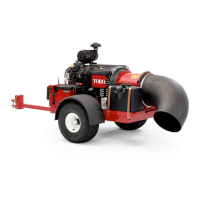
ProForce®DebrisBlower
18237SLRevA