FuelEvaporativeControlSystem
g275201
Figure10
1.Fueltank
6.Carboncanister11.Barbtting(2each)
2.Grommet7.Hose(3each)12.Hoseclamp(4each)
3.Vent/rollovervalve8.Freshairlter13.Fuellter
4.Hoseclamp(8each)9.Hose–freshair
14.Purgevalve
5.Hose–tanktocarboncanister
10.Hose–canistertolter15.Hose–purgevalvetomanifold
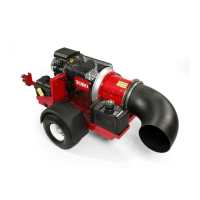
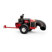
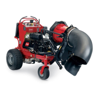
ProForcedebrisblowersareequippedwithafuelevaporativecontrolsystem
designedtocollectandstoreevaporativeemissionsfromthefueltank.The
evaporatecontrolsystemusesacarboncanisterandaseriesofventhosesto
collecttheseevaporativeemissions.Thefueltankusesanon-ventedfuelcap.A
fueltankvent/rollovervalveispositionedinthetopofthetankthatallowstank
ventingthroughthecarboncanister.Fuelvaporsfromthefueltankareventedto
thecanisterandconsumedbytheenginewhentheengineisrunning.
Note:Ifthereisrestrictioninthecarboncanister,thefueltankventttingorthe
venthose,thefueltankmaydistortduetoventingissues.Ifthefueltankreturns
toit’snormalshapewhenthefuelcapisremoved,restrictionintheevaporative
controlsystemislikely.
Thecarboncanisterismountedonthecontroltower/batterybox.The
evaporativesystemconnectiontotheenginepassesthroughalteranda
vacuumcheck/purgevalvebeforeconnectiontotheengineintakemanifold.The
evaporativecontrolsystemventconnectionpassesthroughafreshairlter
beforeitreachesthecarboncanister.
DisassemblingtheFuelEvaporativeControlSystem
RefertoFigure10forthisprocedure.
ProForce®DebrisBlower
Page4–9
Engine:ServiceandRepairs
18237SLRevA
 Loading...


