whentousetheuppermountingholes,referto
10ConnectingthePTOShaft(page15).
SR54andSR54-SAeratorsonly
Note:Thefactoryinstallsthehitchpinsand
lynchpinsontotheSR54andSR54-Saerators
beforeshipping.
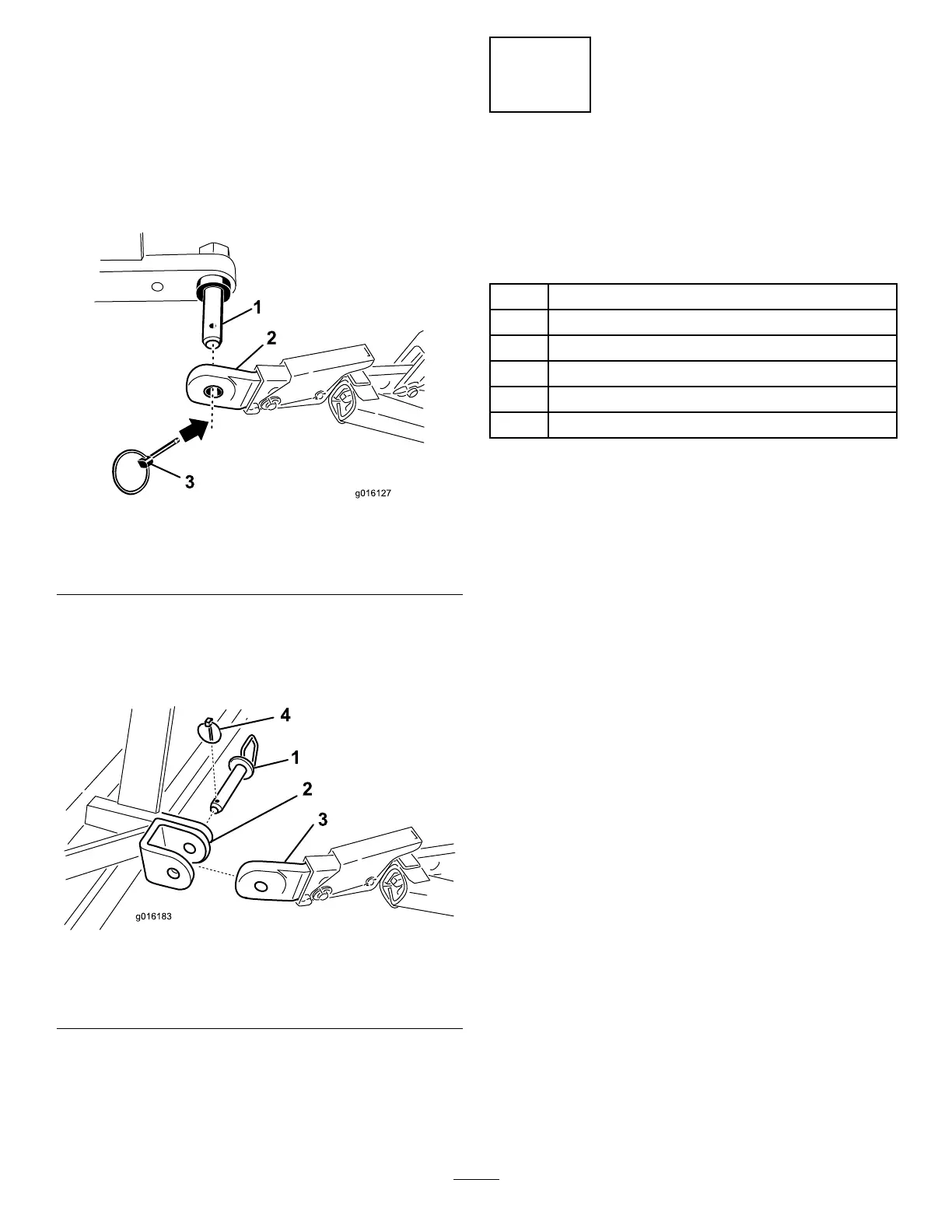
4.Securethelowerlinkarmstotheaerator
mountingpinswithlynchpins(Figure3).
g016127
Figure3
1.Aeratormountingpin3.Lynchpin
2.Lowerlink
SR70,SR70-S,andSR72Aeratorsonly
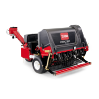
5.Securethelowerlinkarmstotheaerator
mountingbracketswithhitchpinsandlynchpins
(Figure4).
g016183
Figure4
1.Hitchpin3.Lowerlink
2.Aeratormountingbracket4.Lynchpin
3
ConnectingtheHydraulic
TopLink
ModelsSR54,SR70,andSR72
Partsneededforthisprocedure:
1Hydraulictoplink
1
Hydraulichose—106cm(3-1/2ft)
1
Hydraulichose—76cm(2-1/2ft)
2Extensionbracket
1Rotationalbracket
2Hosequickcouplings
Procedure
Note:Makesurethatthesuppliedcouplingsare
correctforthetractionunit.Ifnot,contactthetraction
unitmanufacturertoobtainthecorrectcouplings.
Yourtractionunitmusthaveadoubleacting
spoolvalvewithanoperatorcontrolleverand2
quick-releasecouplings12.7mm(1/2inch)atthe
rearofthetractionunit.Thefactoryprovides2quick
couplingstotontothehydraulictoplinkhoses
(1/2-14NPTFhoseendthreadsize).
Usetheprocedurethatfollowstoinstallthehoses
anddeterminetheneedfortheextensionorrotation
blocks.Thisinformationalsohelpsyoutodetermine
thedepthrangeoftheaerator.
1.Securetheconnectinglinkendofthehydraulic
toplinktothetractionunitwiththepinssupplied
withthetractionunit(Figure5).
Positionthehydraulictoplinksothattherod
endistowardtheaeratorandthecylinderports
aligntowardtheauxiliarypowerhydraulicsof
thetractionunit.
Note:Ifyoumustpositionthehydrauliccylinder
withtheportsfacingupward,usetherotational
blockinsteadofthestandardmountingblockto
repositionthecylinder(Figure5).Youmayuse
a90°hydraulicttinginsteadoftherotational
block(90°ttingsarenotincluded).
Installtherotationalblockasfollows:
A.Removethecotterpinandpinsecuring
thestandardconnectinglinktothecylinder
(Figure5).Removetheconnectinglink
fromthecylinder.
9