118
model 2000 DeviceNet Module Manual (DN611/DN611A)
Chapter 6 RAS Information (Except for RAS Area in Communication Memory)
6
6.1 Module Status (MS)/Network Status (NS) LEDs
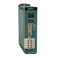
The 2-color light-emitting diode (LED) on the front panel of the DN611 (module status/
network status LED) indicates module status (MS) and network status (NS) in two colors
(green and red) and by ON, blink, and OFF.
Table 6-1 Module Status/Network Status LED
LED Indications Meanings (Main Error)
MS OFF • No power is supplied to the DN611.
• Although power is supplied to the DN611, it is not in
run mode.
If the node address/error code 7-segment LED indicates
the local station node address, power is supplied.
Green ON • DN611 is operating normally.
Green blinking • DN611 is reading switch settings.
Red blinking • DN611 has developed a recoverable error → Switch
setting error (DIP switches/rotary switches), etc.
Red ON DN611 has developed an irrecoverable error (down
state). The module may have to be replaced.
NS OFF • No power is supplied to the DN611 (check MS).
• Although power is supplied to the DN611, it is not in
run mode (check MS).
• DN611 has developed an irrecoverable error (down
state: check MS).
• No network power is supplied to the DN611.
Green ON • DN611 is communicating normally with slave devices.
Green blinking • No communication is established between the DN611
and slave devices.
• Not a single slave device is registered in the DN611.
Red blinking • DN611 is unable to communicate with an abnormal
slave device.
Red ON • Communication halt due to DN611 busoff.
• Communication halt due to a duplicate node address.
 Loading...

