Home
Toshiba
Control Unit
2000 V Series
Page 39 (2 Names and Functions of the Parts of the DN611)
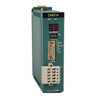
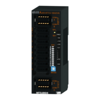
Toshiba 2000 V Series - 2 Names and Functions of the Parts of the DN611; External Views, Dimensions, and Names of Parts
270 pages
Manual
To Next Page
To Next Page
To Previous Page
To Previous Page
Loading...
6F8C0
845
17
2
Chapter 2 Names and Functions
of the Parts of the DN61
1
This ch
apter ex
plains th
e names a
nd func
tions of t
he parts
of the D
N61
1.
2.1 External V
iews, Dimensio
ns, and Names of Parts
Figure 2-
1 Exter
nal View and Di
mensions (
In mill
imeters
)
38
40
Table of Contents
Main Page
Default Chapter
19
Table of Contents
19
1 Overview of the Devicenet Module
23
Features and System Configuration Examples of the Devicenet Module (DN611)
23
Network Configuration of Devicenet
25
Network Configuration
25
Trunk Line/Drop Line and Maximum Cable Length
26
Terminator
28
Applicable Standards and Trademarks
29
Basic Functions
30
Polling Instruction/Response
30
Bit Strobe Instruction/Response
31
Synchronous/Asynchronous Mode and Data
33
Refresh Cycle
33
Specifications of the DN611
35
Function Specifications
35
Number of Mounting Modules
36
2 Names and Functions of the Parts of the DN611
39
External Views, Dimensions, and Names of Parts
39
Functions of the Parts
43
3 Preparations for Operation (Hardware)
45
DN611 Setting Flowchart (Hardware)
45
Setting the Switches
47
DIP Switches for Operation Mode/Communication Rate Setting
47
Rotary Switches for Node Address Setting
49
Mounting in the Base Unit
51
Connection to the Network
52
Connecting Devicenet Cables to Network
54
Connector
54
Connecting Network Connector to the DN611
55
Network Power/Grounding
57
Network Power Supply Method
57
Network Power Configuration Method
58
Network Power Unit (24 VDC)
64
Network Grounding
65
Switching Power on and off
66
Network Components
67
4 Operating Procedures for the DN611 (Software)
69
Registering the DN611
70
S Controller Interface Buffer Memory Configuration
74
Input/Output Data Areas
76
RAS Information Area
80
Data Area
89
Semaphore Area
90
Requests to the DN611
93
DN611 Operation Modes
94
Reset Request
95
Parameter Setting Request (Local Node)
97
Parameter Setting Request (Slave Devices)
100
Operation Mode Control Request
103
RAS Information Read Request
105
Time Setting Request
107
User Function Block for Slave Data Input/Output
108
Input/Output Data Area Batch Access
108
Confirming the Allocations
112
Slave Data Input (Asynchronous Mode Only)
113
Slave Data Output (Asynchronous Mode Only)
115
Completion Status
117
5 Example of Use of the DN611
119
System Configuration of the Example
120
Operating Sequence
121
Slave Data Input/Output
122
Other Functions
134
6 RAS Information (Except for RAS Area in Communication Memory)
139
Module Status (Ms)/Network Status (NS) Leds
140
Indications of the 7-Segment LED
141
RAS Information Read Data
143
RAS Counter
143
Event History
146
Execution Node Information
149
7 Troubleshooting
153
At Module Start
153
Reset Request (Scan List Clear)
154
No Run Mode
155
Data Communication with Slave Devices
157
8 Installation and Wiring
159
Unit
159
Mounting/Removing the Module
160
Power Cable Wiring/Grounding
160
Power Cable Wiring
160
Grounding
160
Network Installation
162
Cabling Outside the Cubicle
162
Cabling Inside the Cubicle
164
A Maintenance and Inspection
165
B READ Instruction/Write Instruction Execution Time
167
100 C Definition of each Request Function
169
Block
169
D Definitions of the Function Block for Slave Data Input/Output
227
E Dn611A
264
Index
267
Related product manuals
Toshiba PA912
116 pages
Toshiba GN-4020
12 pages
Toshiba PNE001Z
63 pages
Toshiba TC Series
84 pages
Toshiba GN-4030-A3
6 pages
Toshiba RBM-A101VAE
52 pages
Toshiba TC200 Series
84 pages
Toshiba 3 axis TB6560
9 pages
Toshiba RBM-SV1121HUPE
14 pages
Toshiba MMW-UP0271LQ-E
15 pages
Toshiba AJ65VBTCU-68ADVN
106 pages
RBM-PMV0363E, RBM-PMV0903E
12 pages