120
model 2000 DeviceNet Module Manual (DN611/DN611A)
Chapter 6 RAS Information (Except for RAS Area in Communication Memory)
6
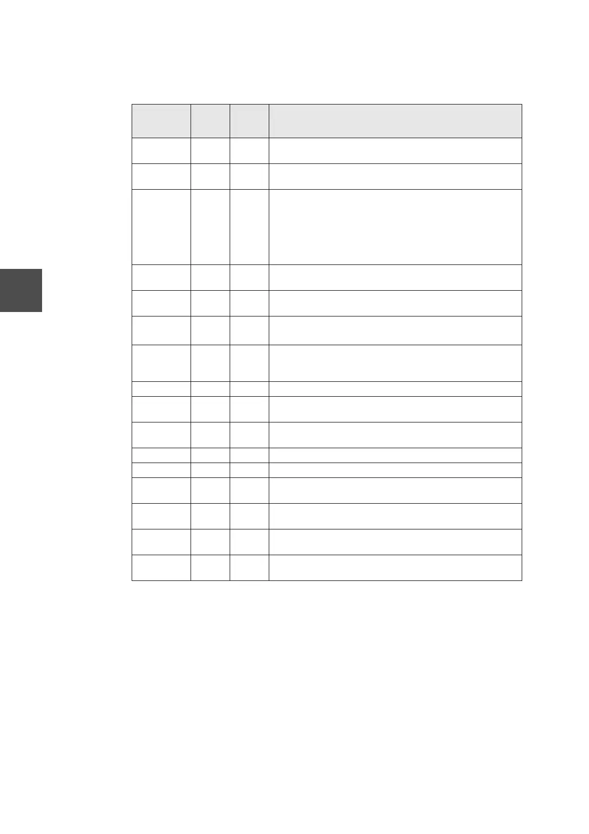
Table 6-3 Combined Indications of the 7-segment LED and 2-Color LED
M: DN611 node address S: Slave device node address
7-segment
LED
MS NS
Description
77 ↔ S Green
ON
Red
blinking
Transmission size different from the actual size has been set
as slave device parameter.
78 ↔ S Green
ON
Red
blinking
Transmission to one or more slave devices on the scan list
cannot be started.
79 ↔ M Green
ON
Red
blinking
• START bit not set to 1 at a run request (followed by the indi-
cation of 78 ↔ S ).
• Response from all slaves has ceased during normal trans-
mission (followed by the indication of 72 ↔ S ).
• No slave device exists on the network when starting trans-
mission (this indication only).
84 ↔ M Green
ON
Green
blinking
Slave devices have not been initialized yet.
91 ↔ M Green
ON
Red ON Busoff has occurred. (Communication halt at busoff was
selected.)
92 ↔ M Green
ON
OFF • Network power is not supplied to the DN611.
• The network connector on the DN611 was disconnected.
A0 ~ CA Unfixed Unfixed When requests to the S controller have ended in an error,
completion status (Table 4-16) is indicated on the 7-segment
LED.
F0 ↔ M Red ON OFF Down mode: Watchdog timeout error
F1 ↔ M Red
blinking
OFF Down mode: Memory bus error
F2 ↔ M Red
blinking
OFF Down mode: TRAP
F3 ↔ M Red ON OFF Down mode: ROM BCC check error (at DN611 start)
F4 ↔ M Red ON OFF Down mode: RAM read/write error (at DN611 start)
F5 ↔ M Red ON OFF Down mode: S controller communication memory read/write
error (at DN611 start)
F6 ↔ M Red
blinking
OFF Down mode: DN611 node address setting error
F7 ↔ M Red
blinking
OFF Down mode: DN611 network communication rate setting error
F8 ↔ M Red
blinking
OFF Down mode: Scan list EEPROM read error

 Loading...


