6F8C0845
59
4.2 S Controller Interface Buffer Memory Configuration
4
Details of the information that can be checked in the RAS information area are explained
below.
(1) Station status (02CEH: 1 word)
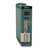
This register indicates DN611 status with bit configuration flags. Each bit is
significant at 1.
Format
Figure 4-11 Station Status Bit Configuration
Table 4-3 on the next page shows examples of station status bit configuration of the
DN611 in different modes.
Table 4-2 Meanings of Station Status Bits
Bit Name Meaning
F DOWN DN611 is in down mode.
E Reserved
D STBY DN611 is in standby mode.
C RUN DN611 is in run mode.
B Reserved
A BITS Transmission is under way in bit strobe mode.
9 POLL Transmission is under way in polling mode.
8 Reserved
7 Reserved
6 NCOIN No slave device is registered in the DN611.
5 TXERR Some of the salve devices registered do not respond.
4 START DN611 is transmitting.
3 SYNC DN611 is operating in synchronous mode.
2 BUSOFF DN611 is in busoff status.
1 DPADR DN611 detected an duplicate node address when starting transmission.
0 Reserved
F E D C B A
9 8 7 6 5 4 3 2 1 0
DOWN STBY Reserved POLL Reserved TXERR SYNC DPADR
Reserved RUN BITS Reserved NCOIN START BUSOFF Reserved
 Loading...

