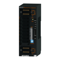
1.2 Names and Functions of the Parts
Unified Controller nv series PROFIBUS(PA912) Module Instruction Manual
11
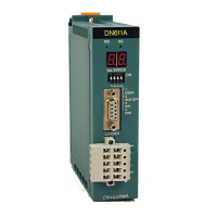
Maintenance switch
MAINT switch is used to insert or remove the TC-net I/O loop cable.
For details, refer to "Chapter 2 Installation and Wiring."
CAUTION
Maintenance switch is used only for inserting or
removing the TC-
net I/O loop cable. Do not use it
when PA912 is operating.
Mandatory
Serial communication port
Tool port is an RS-232C port for Toshiba’s maintenance. The connector is a
9-pin D-sub connector (socket).
CAUTION
Do not connect any cables to the serial
communication port.
Otherwise, PA912 may go wrong.
Mandatory
PROFIBUS state display LED
Table 1-4 Display details on the PROFIBUS state display LED
CFG (green/red) ON (green): Configuration data OK
Blinking (green): Configuration data download in progress
ON (red): Configuration data invalid
OFF: No Configuration data downloaded
COM (green/red) ON (green): Data exchange with all configured slaves
Blinking (green): Data exchange with at least one
configured slave
ON (red): Bus control error
OFF: No data exchange with any of the
configured slaves
MODE(green/red)
ON (green): Operate mode
Blinking (green): Clear mode (Output data is zero)
ON (red): Stop mode
OFF: Offline
TOK (green) ON: The module has the token
OFF: The module does not have the token
(Note) 1. Check the LED states from the front.
Note
•
When the maintenance switch is set to the maintenance state (MAINT), all LEDs go off.
PROFIBUS configurator tool port
CONFIG port is to connect the HMS configurator tool and set the slave I/O of
PROFIBUS.
For details, refer to "Chapter 3 3.2 Setting the Slave Device Configuration
Information."

 Loading...

