Chapter 3 Setting
6F8C1259
3.1 Switch Setting
The switches that determine the operation mode and TC-net I/O loop address
of PA912 are on the BU90A unit.
The method to set the switches is shown below.
Important
•
Set the switches that determine the operation mode and station address of the PA912 module
before turning the power on.
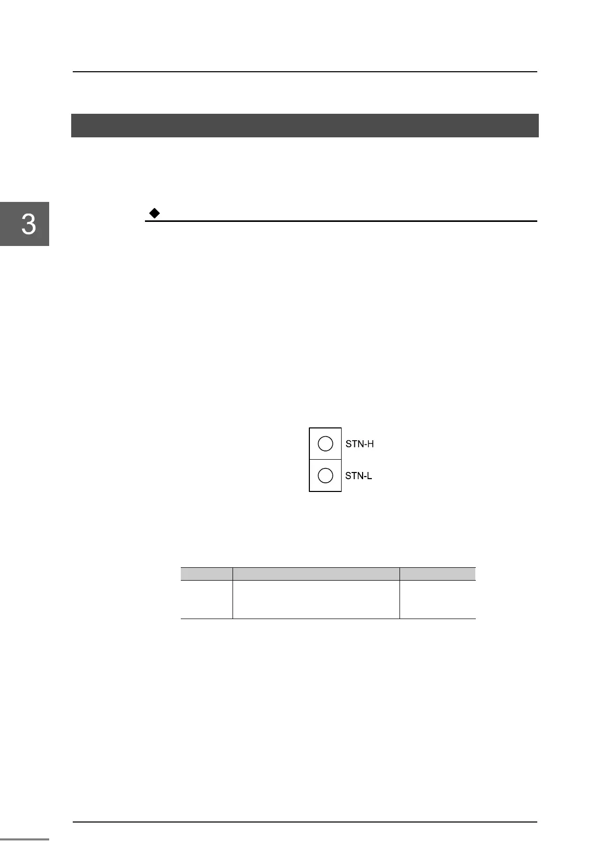
3.1.1 TC-net I/O loop address setting switch (STN-H, STN-L)
TC-net loop address setting switches are hexadecimal rotary switches that
determine the loop address on the TC-net I/O loop.
Set the station address (3 to 34) that has been assigned upon system
configuration in a HEX code (03 to 22 (h)). Assign an address with a different
value to each of the nodes in the system.
Table 3-1 shows the setting of a TC-net I/O loop address.
Figure 3-1 TC-net I/O loop switch setting configuration
Table 3-1 TC-net I/O loop address setting
Name Description Remark
Setting range : 03 to 22(h)
STN-H(upper digit address): 0 to F(h)
STN-L(lower digit address): 0 to F(h)
00h is set as a
factory default
STN-H
STN-L
(Note) (h) indicates hexadecimal.
Set the station address in hexadecimal.
For example, if the address value is 28, it is ‘1C’ (h) when converted to
hexadecimal. Therefore, set as follows:
STN-H side: ‘1’
STN-L side: ‘C’
For decimal-hexadecimal conversion, refer to "Appendix D
Decimal-hexadecimal conversion table."
 Loading...


