Chapter 1 Introducing the PA912 Module
6F8C1259
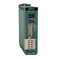
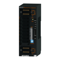
1.2.2 Functions of the parts
The major functions of the parts are as shown below.
TC-net I/O loop state display LED
Table 1-3 Display details on the TC-net I/O loop state display LED
RUN(green) ON: Module is normal or waiting for parameter download
OFF: Module is abnormal
ERR(red) ON: Module is abnormal
OFF: Module is normal
LP(green) ON: TC-net I/O loop is normal
OFF: Disconnection of TC-net I/O loop exists
SCAN(green) ON: TC-net I/O loop side scan transmission is running
normally
OFF: TC-net I/O loop side scan transmission is in
suspension
Blinking: TC-net I/O loop side scan block is overlapping
LNK1(green) ON: LP1 Link established (normal)
OFF: LP1 No link established (abnormal)
ACT1(green) Blinking: LP1 Transmission is running (normal)
OFF: LP1 No transmission is running (abnormal)
LNK2(green) ON: LP2 Link established (normal)
OFF: LP2 No link established (abnormal)
ACT2(green) Blinking: LP2 Transmission is running (normal)
OFF: LP2 No transmission is running (abnormal)
(Note) 1. Check the LED states from the front.
Note
•
When the maintenance switch is set to the maintenance state (MAINT), all LEDs go off.
TC-net I/O loop connector
LP1 and LP2 are the connectors for TC-net I/O loop optical cable. For the
details, refer to "Chapter 2 Installation and Wiring."
TC-net I/O loop address setting switch
STN-H and STN-L are the switches to set the address on the TC-net I/O loop in
hexadecimal. For the setting method, refer to "Chapter 3 Setting."
Mode setting switch
MODE is the switch to set the operation mode of the PA912. For the setting
method, refer to "Chapter 3 Setting."

 Loading...

