3.1 Switch Setting
Unified Controller nv series PROFIBUS(PA912) Module Instruction Manual
31
3.1.3 Maintenance switch (MAINT)
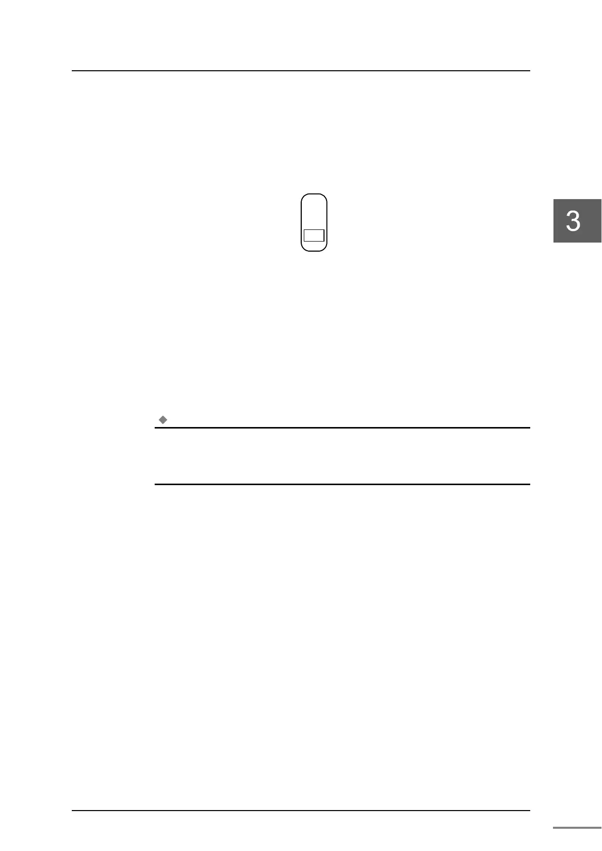
Figure 3-3 shows the maintenance switch configuration.
Figure 3-3 Maintenance switch configuration
The switch is operated only to insert or remove the TC-net I/O transmission
cable or PROFIBUS transmission cable.
Before inserting or removing cables, set the switch to up (MAINT) position to
isolate the module from the system.
After inserting the cable, set the switch to down (RUN) position.
AS a factory default switch is set to be (MAINT) position.
Note
・
Do not insert or remove cables during the PA912 is in operation and the maintenance switch
is set (RUN) position.
◆
◆◆
◆
Important
・
The maintenance switch should be operated with a precision driver.
↓RUN
 Loading...


