A.2 PA912 and BU90A Specifications
Unified Controller nv series PROFIBUS(PA912) Module Instruction Manual
87
A.2 PA912 and BU90A Specifications
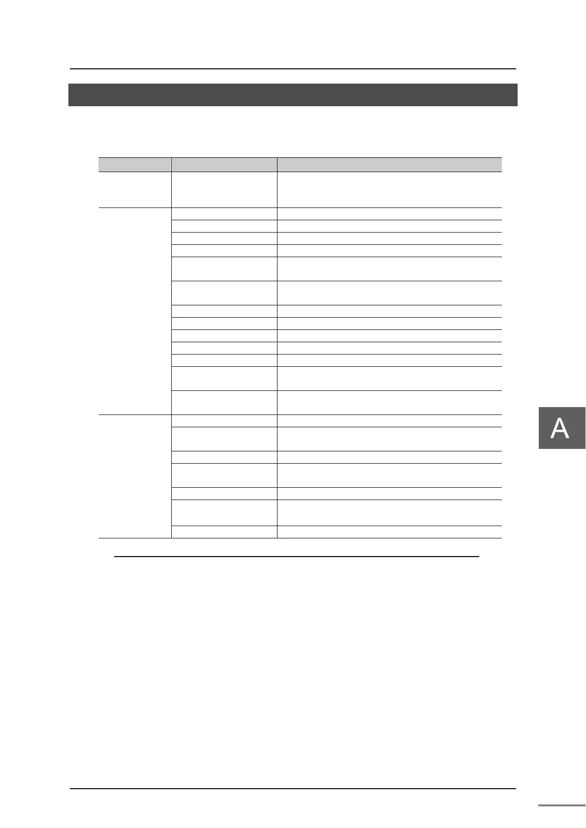
Table A-3 shows the specifications of PA912 and BU90A
Table A-3 PA912/BU90A specifications
Performance
specification
Fault detection Watchdog timer error
Memory ECC error (common memory)
Bus timeout error, etc.
TC-net I/O
loop
specification
System Optical
Topology Loop
Transmission speed 100Mbps
Redundancy Single loop only
Number of nodes
connected
Up to 254 nodes
Number of I/O adaptors
connected
Up to 32 adaptors
Transmission cable Optical fiber (core diameter/clad 50/125, 62.5/125)
Connection connector Optical module
Maximum cable length 2km
Total extension 4km
Communication service Scan transmission/message transmission
Scan cycle
High-speed scan: 100µs or more
Middle-speed scan: 1ms or more
Scan transmission
capacity
64kW/system (1024 blocks/system)
Maximum transmission capacity 32kW/node
Module
specification
Cooling method
Natural air cooling
Dimensions
PA912: 35 × 185 × 95mm
BU90A: 72 × 200 × 30mm
Weight PA912 + BU90A: 500g or less
Power voltage range 20.4 to 26.4VDC (24VDC+10% -15%)
Supplied from the BU90A power supply terminal block
Power terminal M3.5 screw terminal block (BU90A)
Current consumption
(when rated power is fed)
0.5A or less (24VDC) for a PA912
Communication interface
PROFIBUS-DP
◆
◆◆
◆
Important
・
The PA912 is restricted to use the combination of the versions between PA912 firmware
and the GSD.( See the combination versions described in "Chapter 1.1: Functions and
Characteristics of the PA912 Module".).If the correct combination of versions is not used,
the input and output data is set to be incorrect.
・
To avoid to use the incorrect combination of the versions PA912 firmware and Gsd. Confirm
the versions of the PA912 firmware version with nV-Tool.
・
To enable byte-swapp mode,PA912 firmware version V2.20 or later and nV-tool version also
4.8.3 or later
 Loading...


