Chapter 2 Installation and Wiring
6F8C1259
CAUTION
When using it in an environment with
extreme vibrations, insert a cushion rubber
cap (ADP901) or other cushion material
between the base unit and DIN rail stopper.
This will prevent damage and scratch of the case.
Mandatory
2
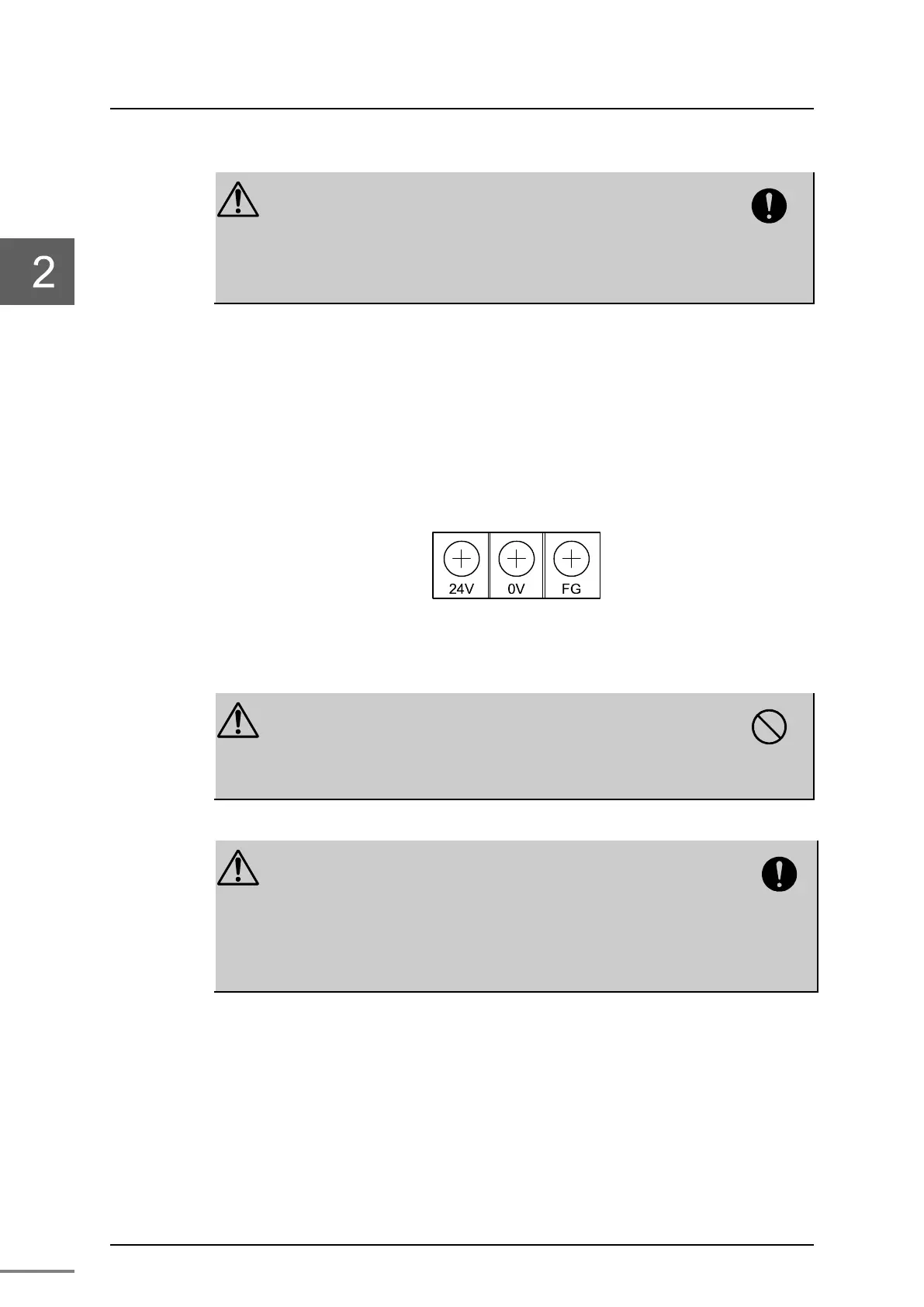
Connect the power terminal block of the base unit (BU90A) of the
PA912.
Connect 24VDC, 0V, and FG (D-class grounding with ground resistance of 100
Ω or less dedicated ground) to the power terminal block of the base unit
(BU90A) of the PA912. (the screw size for these wiring terminals is M3.5).
Figure 2-2 Power terminal block of the base unit BU90A
CAUTION
Do not share the 24VDC power supply for the
BU90A with the power supply for other I/O.
If it is shared with the power supply for other I/O,
it may cause malfunction or failure of the modules.
Prohibited
CAUTION
For DC24V power supply to the BU90A, refer
“Appendix A.4 DC24V system power supply
specifications.”
If the I/O power supply
other than the specification is
used, it may cause malfunction or failure of the
module.
Mandatory
 Loading...


