– 21 –
Connecting wire
(accessory)
Clamp filter
Timer terminalPower terminal
Schedule
timer
Wired
remote
controller
: Connector
4 wires
DC12V
: Terminal board
Schedule
timer
Wired
remote
controller
Indoor
unit
Outdoor
unit
U1
U2
Wire joint
(Not used)
BlueBlue Pink
Power terminal
(4P connector)
Communication
terminal (3P connector)
Schedule timer
Connecting wire (accessory)
Clamp filter
Field supply
64 system central remote controller
(Back side)
Communication
wiring
(blue + pink)
Inter-unit control wiring
U1
U2
U3
U4
U1
U2
P1
U3
U4
U1
U2
U3
U4
U1
U2
U3
U4
U1
P1
L1
L3
4L2L
P1
U2
U1
U2
To power terminal
To communication
terminal
To power terminal
To communication
terminal
To power terminal
To communication
terminal
64 system central remote controller or
ON-OFF controller
Indoor unit
(Header unit)
Outdoor unit
(Header unit)
Outdoor unit
TCC-LINK
adapter
Indoor
unit
Wiring
specifications (1)
Wiring specifications (2)Wiring specifications (2)
Remote
controller
Remote
controller
Remote
controller
Remote
controller
Schedule
timer *2
Schedule
timer *3
Indoor
unit
Indoor
unit
Indoor
unit
Refrigerant system 3
(S-MMS)
Refrigerant system 2
(SDI/DI)
Refrigerant system 1
(S-MMS)
Schedule timer *1
U2
U4
U1
U3
CN61(T10)
1. Supplied parts
Indoor unit control PCB
Field supply
Wire joint
(Not used)
Indoor/Outdoor units communication line
(for S-MMS)
Central control system wiring
(for SDI/DI)
(for SDI/DI)
(for S-MMS)
BlueBlue Pink
Communication
wiring
(blue + pink)
Power wiring
(black + white)
Power terminal
(4P connector)
Communication
terminal (3P connector)
Schedule timer
Black White
How to wire the remote controller
Wiring diagram
Basic diagram
Wiring specifications (1)
If a 64 system central remote controller (or ON-OFF
controller) is installed (power is supplied from the 64
system central remote controller):
System diagram
When installing multiple schedule timers, avoid the
use of communication line.
Connection diagram (Be sure to use the provided
wires as the power wiring.)
Wiring procedures
Connect the provided connecting wire to the power
terminal (4P connector) of the schedule timer.
The terminal attached to the clamp filter must be
connected to the schedule timer.
The length of the power wiring must be no more
than 100 m.
Wiring specifications (2)
If a 64 system central remote controller (or ON-OFF
controller) is not installed (power is supplied from the
indoor unit):
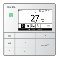
5. Weekly schedule Timer
2.7
120
120
4
16
DI
SDI
MiNi-SMMS
SMMS
SHRM
SMMS-i
SHRM-i
OK
OK
OK
OK
OK
OK
OK
Category
Type Name : TCB-EXS21TLE
Part No. : Not assigned
Substitution : NO
Type of Remote : Schedule Timer
Reference : NO
Product used : VRF
Note : *4 way
*Duct
*Ceiling

 Loading...