Do you have a question about the Toshiba Satellite A350 and is the answer not in the manual?
Indicates hazard with death or serious bodily injury risk if instruction not observed.
Indicates hazard with bodily injury risk if instruction not observed.
Indicates hazard with property damage risk if instruction not observed.
Contains general information related to safe maintenance service.
Defines acronyms upon first appearance for clarification.
Describes how key top symbols are printed in the text.
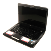
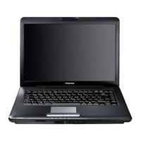
Lists the key features and specifications of the computer.
Details the specifications of the 2.5-inch Hard Disk Drive.
Describes the DVD Super Multi drive and its capabilities.
Explains the functions and status display of the power supply unit.
Details the types of batteries and their charging control mechanisms.
Introduces how to determine if an FRU is causing a computer malfunction.
Provides a flowchart guide for determining troubleshooting procedures.
Outlines procedures for diagnosing and resolving power supply issues.
Details steps to troubleshoot display problems.
Provides steps to diagnose and resolve keyboard issues.
Guides on troubleshooting external USB device functionality.
Outlines procedures for diagnosing and fixing touch pad problems.
Details troubleshooting steps for the Ultra-Wideband (UWB) module.
Provides steps to troubleshoot built-in speaker functionality.
Outlines procedures for diagnosing and resolving optical drive issues.
Details troubleshooting steps for the computer's modem.
Guides on troubleshooting issues with the Express Card slot.
Outlines procedures for diagnosing and resolving IEEE 1394 port issues.
Provides steps to troubleshoot wireless LAN connectivity.
Guides on diagnosing and fixing camera problems.
Details troubleshooting steps for Bluetooth functionality.
Outlines troubleshooting for the bridge media card slot.
Provides steps to diagnose and resolve Hard Disk Drive issues.
Guides on troubleshooting problems with the CRT port.
Details troubleshooting steps for the HDMI port.
Outlines procedures for diagnosing and resolving SPDIF issues.
Guides on troubleshooting microphone functionality.
Details troubleshooting steps for the fingerprint sensor.
Outlines troubleshooting for the FM tuner component.
Guides on diagnosing and fixing E-SATA port issues.
Details troubleshooting steps for the Felica module.
Outlines procedures for diagnosing and resolving sensor button problems.
Guides on troubleshooting issues with the computer's LEDs.
Details troubleshooting steps for the thermal module.
Outlines procedures for diagnosing and resolving TV-out issues.
Provides steps to troubleshoot LAN connectivity.
Explains how to use the Test & Diagnostic program for hardware module testing.
Provides steps to start and run the diagnostic programs.
Shows how to display unit configuration details.
Tests speaker function by generating beep sounds.
Tests fan operation by turning it on and off.
Tests the main battery's charge function and capacity.
Tests the Floppy Disk Drive functionality through subtests.
Checks DDR RAM vendor, frequency, and size for correctness.
Tests the functionality of all keys on the keyboard.
Allows users to test touch pad functions like speed and button assignments.
Checks video display quality in different text and VGA modes.
Tests the lid switch function to turn off the display.
Checks the LAN full-duplex environment.
Checks RTC and calendar functions by comparing DOS and CMOS values.
Checks if the EEPROM 1394GUID code is correct.
Checks and rewrites EEPROM EQ type for speaker quality.
Allows manual testing of each sensor button.
Verifies if the HDCP key is written successfully to the computer.
Verifies the functionality of the first Hard Disk Drive.
Verifies the functionality of the second Hard Disk Drive.
Reads and displays system DMI data such as serial number and product name.
Allows writing DMI data like OEM string, version, serial, and product.
Configures the Front Edge Logo function, enabling or disabling it in BIOS.
Explains how to disassemble the laptop and replace Field Replaceable Units (FRUs).
Details procedures for removing and installing the battery pack.
Provides instructions for removing and installing Hard Disk Drives.
Details procedures for removing and installing optional memory modules.
Explains how to remove and install the Wireless LAN card.
Details procedures for removing and installing the modem card and FM tuner.
Provides instructions for removing and installing the Optical Disk Drive bay module.
Details procedures for removing and installing the keyboard cover and keyboard.
Describes how to remove and install the logic upper assembly.
Details procedures for removing and installing the power board.
Provides instructions for removing and installing the speakers.
Details removal and installation of touch pad, LED, and fingerprint boards.
Provides instructions for removing and installing the thermal fan.
Details procedures for removing and installing the motherboard.
Describes how to remove and install the Ultra-Wideband module.
Provides instructions for removing and installing the Robson module.
Details removal and installation of VGA board and thermal module.
Provides instructions for removing and installing the CPU and thermal module.
Details procedures for removing and installing the display assembly.
Describes how to remove and install the LCD bezel assembly.
Details procedures for removing and installing the LCD module and inverter board.
Provides instructions for removing and installing the CMOS board and microphone.
Details procedures for removing and installing the hinge saddle.
Describes how to remove and install the CRT board.
Provides instructions for removing and installing the USB board.
Details procedures for removing and installing the FM jack.
Describes how to remove and install the Bluetooth card.
Highlights critical safety warnings regarding batteries and high voltage components.
Provides safety warnings related to electrical shock and sharp edges.
Lists cautions for component replacement, screw usage, and handling hot parts.
Advises on preparation and precautions before starting laptop disassembly.
Explains how to remove pressure plate and normal pin connectors.
Provides guidelines for reassembling the laptop after repairs.
Lists necessary tools and ESD equipment for disassembly/reassembly.
Specifies torque values for securing screws to avoid damage.
Explains how screw shank colors identify correct screws by length.
Describes symbols used on the laptop body to represent screw types and lengths.
Details the steps to remove the battery pack from the laptop.
Details the steps to install a new or recharged battery pack.
Provides instructions for removing the main and second Hard Disk Drives.
Details the steps for installing the main and second Hard Disk Drives.
Details the steps to remove the optional memory module.
Details the steps to install the optional memory module.
Details the steps to remove the Wireless LAN card.
Details the steps to install the Wireless LAN card.
Details the steps to remove the modem card.
Details the steps to remove the FM tuner.
Details the steps to install the modem card.
Details the steps to install the FM tuner.
Details the steps to remove the Optical Disk Drive bay module.
Details the steps to install the Optical Disk Drive bay module.
Details the steps to disassemble the Optical Disk Drive.
Details the steps to assemble the Optical Disk Drive.
Details the steps to remove the keyboard cover and keyboard.
Details the steps to install the keyboard cover and keyboard.
Details the steps to remove the logic upper assembly.
Details the steps to install the logic upper assembly.
Details the steps to remove the power board.
Details the steps to install the power switch board.
Details the steps to remove the speakers.
Details the steps to install the speakers.
Details steps to remove touch pad bracket, LED, and fingerprint boards.
Details steps to install touch pad bracket, LED, and fingerprint boards.
Details the steps to remove the thermal fan.
Details the steps to install the thermal fan.
Details the steps to remove the motherboard.
Details the steps to install the motherboard.
Details the steps to remove the Ultra-Wideband module.
Details the steps to install the Ultra-Wideband module.
Details the steps to remove the Robson module.
Details the steps to install the Robson module.
Details steps to remove VGA board and thermal module.
Details steps to install VGA board and thermal module.
Details steps to remove CPU and thermal module.
Details steps to install CPU and thermal module.
Details the steps to remove the display assembly.
Details the steps to install the display assembly.
Details the steps to remove the LCD bezel assembly.
Details the steps to install the display mask for the LCD bezel.
Details steps to remove LCD module and inverter board.
Details steps to install LCD module and inverter board.
Details the steps to remove the CMOS board and microphone.
Details the steps to install the CMOS board and microphone.
Details the steps to remove the hinge saddle.
Details the steps to install the hinge saddle.
Details the steps to remove the CRT board.
Details the steps to install the CRT board.
Details the steps to remove the USB board.
Details the steps to install the USB board.
Details the steps to remove the FM jack.
Details the steps to install the FM jack.
Details the steps to remove the Bluetooth card.
Details the steps to install the Bluetooth card.
Lists precautions to prevent damage when handling the LCD module.
Shows the layout of components and connectors on the top side of the system board.
Shows the layout of components and connectors on the bottom side of the system board.
Lists integrated circuits on the system board with their numbers and names.
Lists system board connectors with their numbers and names.
Lists pin assignments for the FAN connector.
Lists pin assignments for the FM connector.
Lists pin assignments for the LVDS connector.
Lists pin assignments for the CRT connector.
Lists pin assignments for the HDMI connector.
Lists pin assignments for the 1st HDD connector.
Lists pin assignments for the 2nd HDD connector.
Lists pin assignments for the SATA ODD connector.
Lists pin assignments for the eSATA/USB connector.
Lists pin assignments for the Bluetooth connector.
Lists pin assignments for the Finger Printer connector.
Lists pin assignments for the Felica connector.
Lists pin assignments for the internal camera connector.
Lists pin assignments for the Wi-Fi/WiMax connector.
Lists pin assignments for the Robson connector.
Lists pin assignments for the New Card connector.
Lists pin assignments for the LAN connector.
Lists pin assignments for the LED/B connector.
Lists pin assignments for the GPS connector.
Lists pin assignments for SODIMM connectors.
Lists pin assignments for the internal microphone connector.
Lists pin assignments for the TV-OUT connector.
Lists pin assignments for the HEADPHONE connector.
Lists pin assignments for the keyboard connector.
Lists pin assignments for the USB connector.
Lists pin assignments for the USB/B connector.
Lists pin assignments for the FUN/B connector.
Lists pin assignments for the POWER/B connector.
Lists pin assignments for the CARD READER connector.
Lists pin assignments for the VGA/B connector.
Lists pin assignments for the EXMIC connector.
Lists pin assignments for the 1394 connector.
Lists pin assignments for the EC DEGUB connector.
Lists pin assignments for the 3G CARD connector.
Lists pin assignments for the SPKL connector.
Lists pin assignments for the SPKR connector.
Lists pin assignments for the EXROM connector.
Lists pin assignments for the T/P connector.
Lists scan codes for keyboard keys in set 1 and set 2.
Lists scan codes for keyboard keys in set 1 and set 2.
Lists scan codes for keyboard keys in set 1 and set 2.
Lists scan codes for keyboard keys in set 1 and set 2.
Shows scan codes when the left Shift key is used.
Lists scan codes for keys when Numlock mode is active.
Lists scan codes for keys when the Fn key is used.
Lists scan codes for keys in overlay mode.
Lists scan codes for key No. 124.
Lists scan codes for key No. 126.
Displays the layout of a US keyboard.
Displays the layout of a Traditional Chinese keyboard.
Displays the layout of a Thai keyboard.
Displays the layout of a Korean keyboard.
Displays the layout of a UK keyboard.
Displays the layout of a US International keyboard.
Displays the layout of a Hebrew keyboard.
Displays the layout of a Danish keyboard.
Displays the layout of a Swiss keyboard.
Displays the layout of an Arabic keyboard.
Displays the layout of a Czech keyboard.
Displays the layout of a Russian keyboard.
Displays the layout of a Portuguese keyboard.
Displays the layout of a Slovakian keyboard.
Displays the layout of an Italian keyboard.
Displays the layout of a French keyboard.
Displays the layout of a German keyboard.
Displays the layout of a Greek keyboard.
Displays the layout of a Canada French keyboard.
Displays the layout of a Hungarian keyboard.
Displays the layout of a Spanish keyboard.
Displays the layout of a Turkish keyboard.
Displays the layout of a Turkish F keyboard.
Displays the layout of a Swedish keyboard.
Displays the layout of a Belgian keyboard.
Displays the layout of a Yugoslavian keyboard.
Displays the layout of a Norwegian keyboard.
Displays the layout of a Scandinavian keyboard.
Displays the layout of a Canadian Multinational keyboard.
Displays the layout of a Canadian Bilingual keyboard.
Displays the layout of a Japanese keyboard.
Displays the layout of a Romanian keyboard.
Displays the layout of a Bulgarian keyboard.
Lists screw part numbers, specifications, quantities, locations, and torque.
Shows Mean Time Between Failures (MTBF) for various computer components.
| Processor | Intel Core 2 Duo |
|---|---|
| RAM | 4 GB |
| Graphics | ATI Mobility Radeon HD 3470 |
| Operating System | Windows Vista |
| Optical Drive | DVD SuperMulti |
| Wireless | 802.11a/g/n |
| Card Reader | 5-in-1 |
| Screen Resolution | 1280 x 800 |
| Weight | 2.7 kg |
| Ports | 3x USB 2.0, VGA, HDMI, eSATA |